50
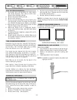
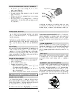
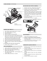
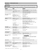
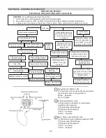
Power On
Is the water
temperature displayed?
NO
YES
Push
MODE
switch to select
"
Pool
" or "
SPA
"
Push Temp
arrow to scroll to
desired temperature
NO
Water temperature
and set
temperature
displayed?
YES
CFH
(call for heat)
or “
Heating
” will
display briefly
NO
NO
YES
YES
Flame icon displayed
and flashing?
OR
Water temp displayed?
(pilot lit and rectified)
Heater Fired?
END
• Check On/Off switch (under lid on control panel)
• Check for 120/240 volts to the transformer
(time clock, circuit breaker, wire connections)
• Check for 24 volts to Circuit Board (P6 connector)
REM and Water Temperature
displayed and flashing
(a remote control is controlling the heater)
Note: Disconnect the remote by turning the remote
function off. See page 36 or page 40 for instructions.
NO
YES
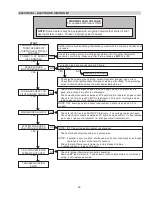
Is SERVICE or a fault code displayed and flashing?
Diagnostic Readouts
"
SNS
" or “
Sensor Failure
,” “
Sensor Open
” or “
Sensor Short
” -
Temperature sensor out of range (replace sensor)
Verify power at MV on P-4 Terminal on digital circuit board.
Verify power to valve MV voltage. (Replace valve.)
SPK
or “
Spark
”
Sensor Failure
Inspect thermister, wires, and connector at Terminal P1
Check resistance value of the thermister. Reference to chart below.
Replace thermister if not within 10% of values shown below.
If okay, replace Circuit Board.
Temp Degrees F 40 50 60 70 80 90 100 106
Resistance (k)
261.1 199.0 153.1 118.8 93.0 73.3 58.3 51.0
If okay, replace Circuit Board
Sensor resistance at various temperatures
PRS
or “
Water Sw Open
”
Pressure switch. Verify water flow and pressure
CLEAN FILTER / STRAINER - backwash if neccessary.
HL1
or “
Hi Limit 1 Fault
”
High limit switch. Verify water flow. Inspect internal
HL2
or “
Hi Limit 2 Fault
”
Thermostat (Unitherm Governor) and bypass valve.
ROL
or “
Rollout Sw Open
”
Rollout Sensor - Check for blocked heat exchanger and soot.
Atmospheric Units - Replace fusible link.
Lo NOx Units - Press manual reset button.
CLK
or “
Clock/Fireman Sw
” Fireman or Remote switch connected to safety loop is in the
OFF mode.
VNT
or “
Vent/Field Sw #1
”
Vent switch open. Check connections to the board.
If extractor installed, troubleshoot extractor.
ILO
or “
Ignition Lockout
”
Ignition lockout. Check power at pilot valve. Check spark (bad
ignition circuit or hi-tension wire). Verify clean pilot orifice and
clearance from igniter to ground hood.
IGN
or “
Ignition Failure
”
Ignition failure. Verify gas to the heater. Verify valve operation
(gas present at tube fitting).
DIGITAL/AFT CONTROL LOGIC - FLOW CHART
Summary of Contents for 206A
Page 28: ...28 WIRING DIAGRAM MILLIVOLT MECHANICAL THERMOSTAT ...
Page 29: ...29 WIRING DIAGRAM DIGITAL MODELS ATMOSPHERIC ...
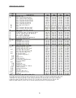
Page 53: ...53 LO NOx HEATERS ...
Page 60: ......


