background image

Chapter 5: Maintenance and Troubleshooting

71

the wiring may be pinched or bent.  Look for signs that water has
gotten into the cable.  If the transducer cable is damaged, the
transducer and cable should be replaced as a unit.  Contact your
Raymarine dealer for instructions.

The display unit does not see the bottom or fish –

1. Be sure the display unit is not using the Simulation mode.  (If this is

the case, the word “Simulation” will flash on the display.)

2. On a unit with the transom-mount transducer, the transducer may

have “kicked up” because it hit an obstruction.  See Fig. 2-8.  Move
the transducer down into the working position.

3. The unit may be set for Manual gain or sensitivity, and be using a

very low sensitivity setting. Adjust the manual gain control, or select
Auto gain.  You can also reset all of the values to the factory defaults,
by holding down the Enter button as you turn on the unit. See the
default settings on page 68.

4. The transducer may not be vertical.  Be sure that the transducer is

aiming straight down, or within 10° of vertical.

5. If the transducer is an in-hull type, be sure that it is installed correctly.

The transducer should be “looking” through just one layer of
fiberglass hull material, no more than 1" (25 mm) thick.  The
transducer should be firmly attached to the hull using the correct type
of adhesive/sealant.

6. The face of the transducer may be covered or fouled.  Use a stiff

brush to clean it.  You may also sand the surface with a fine-grit wet
or dry sandpaper (#320 grade or finer), but this will affect the
performance of the unit when the boat is moving at higher speeds.

7. If the Fishfinder is using the Auto Sensitivity setting, it may be

reacting to an increase in electrical “noise.”  As the level of noise
increases, the sensitivity automatically adjusts, and the unit can lose
its ability to see the bottom or fish.  Check for problems with the
wiring as described in the section on “Display unit freezes.”

8. The voltage from the power source may be low.  This affects the

transmitting power of the Fishfinder.  Check the connections as
described in the section on “The display unit freezes.”

The Fishfinder does not display fish arches –

1. Be sure the Fish Symbol feature is turned off.  See the instructions

for the System Setup display.

Summary of Contents for L750

Page 1: ...Distributed by Any reference to Raytheon or RTN in this manual should be interpreted as Raymarine The names Raytheon and RTN are owned by the Raytheon Company...

Page 2: ...L750 Fishfinder Operation Handbook Raymarine...

Page 3: ......

Page 4: ...cer 7 Mounting the Fairing Block 8 Installing a Thru Hull Transducer 10 Assembling the Transducer Bracket 11 Positioning the Transom Mount Transducer 12 Mounting the Transom Mount Transducer 13 Mounti...

Page 5: ...Power On and Off 30 Turning the Power On Initial Use 30 Turning the Power On Routine Operation 31 Turning the Power Off 31 Setup Memory and Master Reset 32 Operating Pages 32 DownlookPage 33 Fish Ind...

Page 6: ...ions 63 The Setup Menus 63 Chart Speed Setting 63 Log Reset 64 System Setup Menu 64 Resetting the Unit to Factory Defaults 68 Default Settings 68 Chapter 5 Maintenance and Troubleshooting 69 Cleaning...

Page 7: ...g Position 14 Fig 2 10 Mounting the Transducer 15 Fig 2 11 Installing the Sidelooker Transducer 16 Fig 2 12 Suppression Ferrites 18 Fig 2 13 Mounting the Display 19 Fig 2 14 Flush Mount Installation 2...

Page 8: ...vity Soft Keys 52 Fig 3 16 Range Soft Keys 53 Fig 3 17 Variable Range Marker 53 Fig 3 18 Multi Purpose Soft Keys 54 Fig 3 19 Alarm Soft Keys 55 Fig 3 20 Mark Display 57 Fig 3 21 Sidelooker Feature 58...

Page 9: ...L750Fishfinder InstallationandOperationHandbook vi...

Page 10: ...ewater setalarmsforminimumandmaximumdepth show the shape of the bottom determine whether the seabed is hard or soft measure the speed of the boat and the distance traveled show the water temperature W...

Page 11: ...nd temperature sensors including mounting bracket and hardware M78898 Bronze thru hull transducer with speed and temperature sensors M78923 Optional Accessories Optional accessories are available from...

Page 12: ...ducer for installation in fiberglass hull only where deadrise angle is 10 to 22 M78946 Plastic thru hull transducer Valox plastic with speed and temperature sensors used with depth only transducers M7...

Page 13: ...hown in Fig 2 1 Fig 2 1 Transducer Types Most transducer types can measure the water depth Some of the transducers also have two other sensors a paddle wheel which detects the speed of the boat and a...

Page 14: ...fTransducer Before you begin the installation double check to be sure you have the correct type of transducer Each kind of transducer is designed for a particular type of use In this manual we will in...

Page 15: ...er side of the boat This type of transducer is attached to the bracket of the transom mount transducer Installing aThru HullTransducer This unit may be used with a thru hull transducer Please read thi...

Page 16: ...s section will help you through the most important parts of the installation process If the instructions in the package are different from the notes in this manual follow the packaged instructions Sel...

Page 17: ...t least 6 152 mm of headroom above the transducer The deadrise is the angle or slope of the bottom of the hull in the side to side direction Try to find a mounting location with the smallest deadrise...

Page 18: ...aymarine 1 Measure the deadrise angle of the hull at the selected mounting point 2 Cut the block to a shape which fits the exact contour of the hull The cut out portion can be mounted inside the hull...

Page 19: ...ons inside the cable Never hold the transducer in place by pulling on the transducer cable 5 Apply a thin layer of sealant 1 8 or 3 mm to the transducer between the upper flat surface of the transduce...

Page 20: ...rectly Assembling theTransducer Bracket Follow these instructions if you are installing the transom mount transducer Fit together the two parts of the transducer bracket as shown in Fig 2 6 When the i...

Page 21: ...ansducer near the centerline of the boat If the propeller can be turned to steer the boat allow at least 2 50 mm beyond the swing radius of the propeller This will prevent the propeller from damaging...

Page 22: ...3 Looking at the rear of the boat be sure the bracket is vertical perpendicular to the water line 4 Hold the bracket and the wedge if used against the transom and trace the positions of the screw slo...

Page 23: ...has the clearance shown in Fig 2 9 8 Once the bracket is in the correct position you can tighten the screws Fig 2 9 Correct Mounting Position Vertical transom place wedge this way Average transom angl...

Page 24: ...ansducer to the top of the transom mounting bracket Use the four panhead screws supplied The fit should be snug but do not overtighten the screws 4 If you are installing the optional Sidelooker transd...

Page 25: ...d shaft s For sailboats Install near the centerline of the hull and forward of the leading edge of the keel 2 An in hull transducer may only be installed in a fiberglass hull which is no more than 1 2...

Page 26: ...ipment are mounted closely together in a tight space they may interfere with each other The design and manufacture of this unit follow industry standards for Electromagnetic Compatibility EMC However...

Page 27: ...the Fishfinder power cable If it is necessary to run the transducer cable across any wires make the crossing at a right angle Use only genuine Raymarine cables During the installation do not cut the t...

Page 28: ...the unit This will allow you to test the visibility of the display from several different angles 2 Separate the display unit from the bracket by unscrewing the two attaching knobs 3 Mount the base of...

Page 29: ...the cutout for the display Drill two 1 2 13 mm pilot holes at the two corners shown at the edges of the cutout area 4 Cut along the outline of the opening with a small saw 5 Separate the display unit...

Page 30: ...member this hole must be large enough to accept the cable with the connector attached Do not cut the cable To seal the opening use a feed thru cap where the cable passes through the transom 2 For eith...

Page 31: ...d the two units side by side be very careful not to attach the radar cable to the Fishfinder or vice versa This can cause permanent damage to either unit The cable for the radar unit has white insulat...

Page 32: ...ure only transducer then connects to the pigtail which runs to the transducer connector of the L750 Fishfinder This is shown at left in Fig 2 17 Making the DC Power Connections 1 The display unit is d...

Page 33: ...e a 2 amp in line fuse In line fuses are available at most marine supply stores 5 To prevent any interference or electrical noise separate the Fishfinder power wiring as much as possible from other de...

Page 34: ...t the transducer may not be the same speed that your boat moves through the water The hull of the boat may have a shape which channels water past the transducer at a speed which is faster or slower th...

Page 35: ...ing high or low you can correct for this using the entry for Speed Cal To reach Speed Cal go to the System Setup display This is described in Section 4 The entry for Speed Cal is a percentage An entry...

Page 36: ...lay area The various displays or pages produced by the unit appear here You can step through these pages using the soft keys at the bottom of the display Other kinds of display information may also ap...

Page 37: ...t press the same Soft Key a second time to make a choice or select an option These are called Soft Keys because the functions change from one display to the next and are controlled by the software run...

Page 38: ...Display The Display button allows you to step between the main displays or pages presented by the unit VRM VRM means Variable Range Marker This is a way of finding the depth of an object on the displa...

Page 39: ...ditional functions Turning the Power On and Off Turning the Power On Initial Use When you turn on the power to the Fishfinder for the first time the unit will ask you for some set up information This...

Page 40: ...ypressing theSoftKeylabeledLamp thenusingtheup anddown controlsonthe Trackpad RemembertopresstheEnterkeytosavethenewsetting orthe Clearkeytorestorethepreviouslysavedvalue PressingtheLampkey severaltim...

Page 41: ...it has 3 pages or normal displays These can be used to show different kinds of information Here is a list of the three basic pages Mode Function See page Downlook page Standard operating mode good gen...

Page 42: ...right side of the display show the most recent echoes Some of these echoes indicate fish and others show the bottom As new echoes are received the Fishfinder draws a graph of the bottom The bottom gr...

Page 43: ...t easier to see smaller fish but also may pick up background noise When auto gain or sensitivity is on the Fishfinder chooses the correct sensitivity setting automatically 3 Auto range on R The range...

Page 44: ...play If the Zoom feature is turned on this symbol shows the depth of the top of the zoom area If the Bottom Lock feature is turned on the symbol shows the depth of the top of the viewing area 9 Depth...

Page 45: ...e depth units feet fathoms or meters you have selected on the System Setup display The fish depth indicator is turned off when the fish symbol function is off Bottom of display 14 Bottom indication Th...

Page 46: ...pedmark SeeFig 3 4 Ingeneral alargerarchindicatesalargerfish Thisruleisnotalways true though Let ssaythattherearetwofishofthesamesize oneisclose tothesurface andtheotherisnearthebottom Thefishwhichisc...

Page 47: ...be indicated by a single vertical line When the Fish Symbol feature is turned on a fish will be indicated by a fish shaped symbol on the display In general a larger symbol means a larger fish The symb...

Page 48: ...r the bottom Fig 3 5 Bottom Conditions Now let s look at the other main operating pages Press the Display button On the Soft Keys at the bottom of the display press the button for Window Window Page T...

Page 49: ...g temperature battery Option D Downlooker display with Sidelooker display Depth This is the depth of the bottom directly below the boat Speed This item lists the speed of the boat through the water Ba...

Page 50: ...On the Soft Keys at the bottom of the display press the button for Digital Digital Page The Digital page presents some useful information in large numbers on the display See Fig 3 7 This display is us...

Page 51: ...ture Graph One version of the display presents a graph showing the changes in water temperature over the previous 100 minutes Modifying Displays The Downlook and Window pages can be modified by using...

Page 52: ...r for use in very shallow water Dual frequency These settings use both the 50 kHz and 200 kHz signals at the same time This allows for some of the advantages of both frequencies The dual settings prod...

Page 53: ...ect Soft Key to make your choice The Soft Key for Dual has two choices Press the Soft Key until the choice you want is highlighted Zoom Soft Key The Zoom feature gives you a way of enlarging or magnif...

Page 54: ...fthe zoomedsectionofthedisplay thenumberatthetopofthedisplay showsthedepthatthetopofthezoomedarea Thenumberatthe bottomshowsthedepthatthebottomofthezoomedarea WhentheFishfinderissetforAutoZoom itwillc...

Page 55: ...the standard Downlook display you press the Zoom Soft Key and then press the Soft Key for Zoom On the Zoom display will be added to the Downlook display See Fig 3 10 The other Zoom Soft Keys will not...

Page 56: ...ch has been modified using the Bottom Lock feature The right side of the display shows part of the familiar Downlook image The left side shows the Bottom Lock image The bottom is indicated as a straig...

Page 57: ...the Bottom Lock Soft Key three new Soft Keys appear at the bottom of the display Bottom Lock On Off Use this Soft Key to turn the Bottom Lock feature on or off When you do this the unit will say Init...

Page 58: ...a fish Stronger fish echoes on the A scope display will appear wider Weaker echoes appear as narrow bands closer to the horizontal center of the A scope image Figure 3 14 shows a sample of the A Scope...

Page 59: ...not detailed yet Each of these is dedicated to one particular function Display You can use the Display button to call up the three main pages or displays Figure 3 2 showed the Soft Keys which appear...

Page 60: ...utomatically When using the Auto setting the unit chooses the best sensitivity which will detect fish but will also show a minimum of background noise If the amount of background noise changes due to...

Page 61: ...e Auto Manual When you first press the Range button the Fishfinder asks you to set the range manually Use the upper or lower parts of the Range button to decrease or increase the range If the bottom r...

Page 62: ...30 40 50 60 80 100 150 200 300 400 500 600 800 Note If the Sidelooker feature is turned on there is an extra Soft Key which allows you to set the range for the Sidelooker See Section 4 Fig 3 16 Range...

Page 63: ...h provides backlighting for the display area The same setting also controls the brightness of the lighting used for the keys You can increase or decrease the brightness by pressing the Soft Key then u...

Page 64: ...rm is set to 0 the feature will be turned off When the shallow alarm is set the letter S will appear in the upper left hand corner of the normal displays If you move into shallow water and trigger the...

Page 65: ...sound The unit uses different buzzer tones to indicate fish detected by the 50 kHz and 200 kHz transducers Buzzer The fourth Soft key sets up the Buzzer feature Press the Soft Key several times to see...

Page 66: ...The Mark button allows you to set a vertical marker on the display over a selected point on the bottom See Fig 3 20 As the display scrolls past the vertical line keeps the same position relative to th...

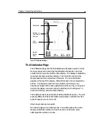
Page 67: ...a bank or pier or into a snag or shallow spot The Sidelooker information will not be displayed unless the Sidelooker feature is turned on To do this go to the System Setup menu Press the Menu button t...

Page 68: ...ds the bottom The display scrolls from top to bottom but this does not necessarily happen at the same speed the boat is moving The speed at which the display moves is set by the Soft Key for Chart Spe...

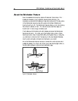
Page 69: ...on this display Boat symbol This shows that the bow of the boat is aiming forward toward the top of the display Centerline The centerline of the boat is lined up with the centerline of the display If...

Page 70: ...Setup display See Fig 4 3 Press the down control on the Trackpad to reach the line labeled Sidelook Press the left control to turn the feature on This unit uses separate settings for the range and gai...

Page 71: ...make a selection IfyouselectManualGain presstheSoftKeylabeledSidelook andusethe up anddown controlsonthetrackpadtochangethesetting Makingthe darkbarlongerincreasesthesensitivity Iftheamountofbackgroun...

Page 72: ...der information moves toward the left of the display If the Sidelooker screen is displayed the new information appears at the top and moves toward the bottom The chart speed adjustment sets the speed...

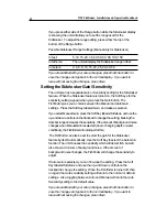
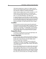
Page 73: ...in the upper left corner of the display On a digital display the log reading will be presented as a large number You can reset the log at any time by pressing the Menu button then selecting the Soft...

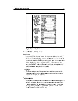
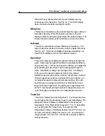
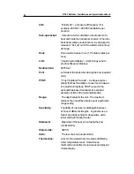
Page 74: ...e is turned on you will see the word Simulation flashing on the display Language When this unit is using the default settings the display uses the English language You may also select French German It...

Page 75: ...adjust the speed reading to make it match your actual speed through the water It presents a reading in percentage points A reading of 100 means the speed readings from the factory default calibration...

Page 76: ...our Kilometers Use the left and right controls to on the Trackpad to change the setting Temp Units This item sets the units used by the temperature display You can choose Fahrenheit degrees F or Celsi...

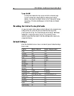
Page 77: ...display the message EEPROM initialization Press the Enter key to exit To go back to normal operation press the Enter button All of the settings will be reset to the values listed below Default Settin...

Page 78: ...ckly on the bottom of the transducer This can reduce the performance in just a few weeks To prevent this coat the bottom of the transducer with a thin layer of paint Use only a water based antifouling...

Page 79: ...adjustment bar is moved all of the way to the left the display will freeze 2 A source of electrical noise may be interfering with the unit s operation Both the transducer cable and the power cable fo...

Page 80: ...10 of vertical 5 If the transducer is an in hull type be sure that it is installed correctly The transducer should be looking through just one layer of fiberglass hull material no more than 1 25 mm t...

Page 81: ...can lose its ability to see the bottom or fish Check for problems with the wiring as described in the section on The display unit freezes The display unit shows lots of background noise 1 The unit may...

Page 82: ...mal Immediately after removing the speed insert place the dummy insert in the transducer housing Do not leave the transducer without the speed or dummy insert in place How to Contact Raymarine For tec...

Page 83: ...ease return the unit to the Raymarine unit from which it was purchased Your Raymarine dealer is best equipped to handle your service needs Service may also be obtained by returning your unit to Raymar...

Page 84: ...Front facia consisting of 1a 1f G625704 1 1 1a Blanking plate 1b Blanking plate seal Part of 1c Window item 1d Window gasket 1e Front cover 1f Light guide green ring 2 Keypad mat lower R112 1 3 Keypad...

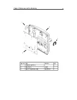
Page 85: ...L750Fishfinder InstallationandOperationHandbook 76 2 3 1 4 Key No Part Part No Qty 1 Keypad PC board upper R113 1 LCD module 1 2 Case seal R070 1 4 Keypad PC board lower R068 1 3 R069...

Page 86: ...Chapter5 MaintenanceandTroubleshooting 77 1 2 3 1 Key No Part Part No Qty 1 Washers part of 2 2 Rear cover 1 2 3 Main PC board assembly G625706 1 1 W095...

Page 87: ...no battery required Power source 10 0 to 16 0 V DC Power consumption backlight off approx 6 W backlight on approx 12 W Dimensions w o bracket 8 H 240 mm x 6 87 W 175 mm 3 27 D 83 mm Weight 3 lbs 14 oz...

Page 88: ...t fathoms meters Numerical display 3 digits Water temperature 32 0 to 99 9 F 0 to 37 0 C Boat speed units Mph kph knots 0 to 70 Sensitivity Auto or manual Connector Diagram Fig 6 1 Connector Diagram V...

Page 89: ...L750Fishfinder InstallationandOperationHandbook 80 Fig 6 2 Dimensions DISPLAY GAIN VRM EBL MULTI MARKS ALARMS RANGE ENTER CLEAR MENU POWER...

Page 90: ...g the up and down controls on the Trackpad Deadrise angle The slope or angle of the underside of the hull measured in the side to side direction Default value A value or setting which is pre loaded in...

Page 91: ...Fluoride A unique polymer plastic that has the ability to convert sound waves into electrical impulses PVDF is used in the optional Sidelooker transducer for excellent detection of fish in the horizo...

Page 92: ...at s hull often a flat panel White Line A feature used to help display fish near the bottom This feature helps to show the difference between weak returns including fish near the bottom and strong ret...

Page 93: ...mpeller carriers impellers impeller bearings and impeller shaft are specifically excluded from this Warranty Magnetrons Cathode Ray Tubes CRT TFT Liquid Crystal Displays LCD and cold cathode fluoresce...

Reviews: