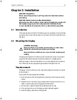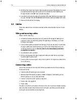
Chapter 3: Installation
23
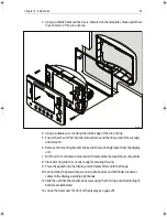
3. Using a suitable hole saw (the size is indicated on the template), make a pilot hole
in each corner of the cut-out area.
4. Using a suitable saw, cut along the inside edge of the cut-out line.
5. Ensure that the unit fits into the removed area and then file around the cut edge
until smooth.
6. Remove the mounting bracket knobs and the mounting bracket from the display
unit.
7. Drill four 4.5
mm holes as indicated on the template to accept the securing bolts.
8. Place trim ring into the cut-out, ready for securing the unit.
9. Place the gasket onto the display unit and press firmly onto the flange.
10.Connect the DC power cable, scanner cable, SeaTalk and Fishfinder connector
cables to the display, avoiding tight bends.
11.Slide the unit into the console and secure using the trim ring and suitable length
bolts (see table below)
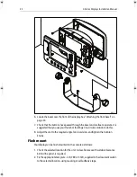
12.Locate the bezel over the front of the display (see
page 24
).
D6738_1
87020-3.book Page 23 Tuesday, March 7, 2006 11:02 AM
Summary of Contents for C120
Page 1: ...C Series Display Installation Manual Document Number 87020 3 Date March 2006...
Page 6: ...iv C Series Displays Installation Manual...
Page 10: ...4 C Series Displays Installation Manual...
Page 16: ...10 C Series Displays Installation Manual...
Page 26: ...20 C Series Displays Installation Manual...


