background image


                             9

What tools do I need to install my TV system?....


Power drill

13 mm (1/2 in)

 socket

10 mm (3/8 in)

 drill

13 mm (1/2in) 

spanner

Socket wrench

80 mm (3 in)

 hole saw

Pencil

Adhesive tape

Cross-head

 screwdriver

5 mm 

Allen key

Suitable waterproof

sealant

D7948_1

Summary of Contents for 45 STV

Page 1: ...Raymarine Satellite TV Systems User s Guide Document Number 81258_3 Date October 2006...

Page 2: ...art Raynav Raypilot Raystar ST40 ST60 Seaclutter Smart Route Tridata and Waypoint Navigation are trademarks of Raymarine Limited DIRECTV is an official trademark of DIRECTV Inc a unit of GM Hughes Ele...

Page 3: ...configure the system 16 Systems with 2RF connector baseplate 16 Single IRD 16 Twin IRDs 17 Multiple IRDs 18 System with 4 RF connector baseplate 21 Multiple IRDs 22 Connecting your satellite TV syste...

Page 4: ...ntroduction 49 Satellite coverage areas 49 Climatic conditions 49 European satellites 49 US satellites 53 Mexico 54 Australia 55 New Zealand 55 Far East 56 Middle East 57 South America 59 Satellite co...

Page 5: ...ad of the power cable CAUTION Antenna unit cover To prevent damage to the antenna unit cover always use the base plate when lifting the unit CAUTION Connectors Take care not to damage the exposed conn...

Page 6: ...2 Raymarine Satellite TV Systems...

Page 7: ...The intended application for Raymarine Satellite TV systems is for leisure marine boats and work boats not covered by IMO carriage regulations THEY ARE NOT intended for installation and use in any oth...

Page 8: ...symbol illustrated above and found on our products signifies that this product should not be disposed of in general waste or landfill Please contact your local dealer national distributor or Raymarin...

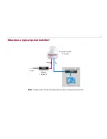
Page 9: ...look like Note Satellitereceivers televisions and subscriptionservices must bepurchased separately Raymarine Satellite TV Antenna Antenna Control Unit Satellite Receiver IRD Television DC Power D7944...

Page 10: ...6 Raymarine Satellite TV Systems...

Page 11: ...least 3 ft 1m from any other equipment transmitting or carrying radio signals In the case of Single Side Band SSB radio the distance should be increased to 7 ft 2m More than 7 ft 2m from the path of a...

Page 12: ...our boat 4 x Hexagonal bolts 4 x Spring washers 4 x Flat washers 4 x Self tapping screws System cables Your Raymarine STV package also includes the following cables RO8134 15 m Power and Data cable us...

Page 13: ...to install my TV system Power drill 13 mm 1 2 in socket 10 mm 3 8 in drill 13 mm 1 2in spanner Socket wrench 80 mm 3 in hole saw Pencil Adhesive tape Cross head screwdriver 5 mm Allen key Suitable wat...

Page 14: ...nsider the following points before installing the system cables All cables need to be adequately clamped and protected from physical damage and exposure to heat avoid running cables through bilges doo...

Page 15: ...hould replace this cable with Raymarine Part No E96007 30 m Power Data cable Power cable This cable is supplied at a length of 10 m RF cable This cable is supplied at a length of 15 m If a longer leng...

Page 16: ...atellite TV Systems How do I install the ACU ACU dimensions The dimensions of the ACU are shown below 195 mm 7 67 in 224 6 mm 8 84 in D9275_1 160 mm 6 3 in 229 mm 9 0 in 195 mm 7 67 in 65 mm 2 56 in 6...

Page 17: ...that the proposed site meets the criteria described above 2 Using the screws supplied fix the mounting brackets to the sides of the ACU 3 Place the ACU in the position where it is going to be installe...

Page 18: ...es of the center hole with a suitable file to avoid damage to the mounting surface Securing the antenna Secure the antenna to the base using bolts spring washers and flat washers The bolts should be t...

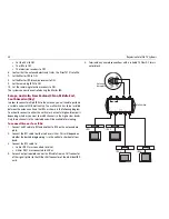
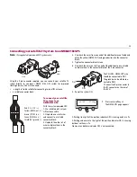
Page 19: ...e antenna 1 Pass the power data cable through the access hole of the mounting plate and connect it to the power data connector on the antenna base plate Note It isgood practice tocoatthe threads of al...

Page 20: ...inations available and their connections In all cases the ACU must be connected to the power data connector of the antenna base plate Systems with 2RF connector baseplate Single IRD This is the basic...

Page 21: ...nes which satellite is tracked while the other receiver can watch any channel which is available from the tracked satellite As in the single IRD option the RF cables from the antenna base plate should...

Page 22: ...some areas DirecTV programming is found on DTV101 and DTV119 local channels When tracking DTV101 all of the receivers can receive programmes from that satellite If you want to see programmes on DTV11...

Page 23: ...0 cm RF cable between Multi S W 18V of the DiSEqC supplier and LHCP 18V of the multi switch 3 Connect a 30 cm RF cable between Multi S W IRD1 of the DiSEqC supplier and any OUT of the multi switch 4 C...

Page 24: ...orizontal high and low pairs depending whether you want to watch channels in the high or low bands Only those channels in the selected band will be available for viewing To connect three or four IRDs...

Page 25: ...ellite receiver The two satellite receiver determines which satellite is tracked while the other receiver can watch any channel which is available from the tracked satellite As in the single IRD optio...

Page 26: ...plate should be connected to LNB ANT or Satellite In on the rear panel of the IRD Systems using more than 4 IRDs To connect more than 4 IRDs you will need to install a suitable active multi switch be...

Page 27: ...end of the additional piece of cable and place the yellow NMEA OUT and ground wires into the connector block 5 Tighten the connector block screws 6 Strip back the wires on the free end of the addition...

Page 28: ...24 Raymarine Satellite TV Systems...

Page 29: ...y of the above functions will only be required at initial installation of your system Note Thesatellitenames shownonthe ACU screeninthefollowing illustrations may differfromthose onyourACUdepending on...

Page 30: ...ASTRA2 B HOTBIRD SETUP D7967_1 TRACKING A ASTRA2 B HOTBIRD SETUP D7969_1 ANTENNA IS UNWRAPPING B HOTBIRD SETUP 4 Antenna is again tracking satellite A Press to display position detail 5 Antenna posit...

Page 31: ...ing set up mode Press YES to set satellite pair 2 Set satellite A Press NEXT to show alternative satellite name Press SELECT to set chosen satellite to SAT A Press EXIT to return to main set up menu 3...

Page 32: ...ess SELECTtosetchosen satellite to SAT A Press EXIT to return to main set up menu D7974_1 SET SAT PAIR PREV YES NEXT D78642_1 SAT A DTV101 NEXT SELECT EXIT D8643_1 SAT B DTV101 NEXT SELECT EXIT 4 Set...

Page 33: ...value Change the underscored digit using the buttons Press INPUT to accept avalue D7973_1 SETUP MODE YES NO D7974_1 SET SAT PAIR PREV YES NEXT D7980_1 SET GPS PREV YES NEXT D7981_1 LONGITUDE 28 20E IN...

Page 34: ...NO D7974_1 SET SAT PAIR PREV YES NEXT D7983_1 EDIT SAT INFO PREV YES NEXT D7984_1 SATNAME ASTRA 2 NEXT SELECT EXIT 5 Input satellite name increases a value decreases a value Change the underscored di...

Page 35: ...INPUT D7991_1 VER HIGH NID 0X0020 INPUT D7992_1 HOR HIGH 11954 27500 INPUT p 14 Input the NID for Horizontal High Band 15 Select the verification method of tracking satellite PREV shows previous metho...

Page 36: ...l for tracking DVB DECODE verify satellite using DVB decoding method for tracking DSS LOCK use only DSS lock signal for tracking AUTO change voltage to LNB by IRD voltage ONLY 13 V always supply 13 V...

Page 37: ...Press NO to cancel and return to main set up menu 1 Press YES to enter set up mode D7998_1 LOCAL FREQ MHZ INPUT D7977_1 SAVE YES NO D7973_1 SETUP MODE YES NO 2 Press NEXT 3 times to enter Local frequ...

Page 38: ...d EXIT returns to main set up menu D7973_1 SETUP MODE YES NO D7974_1 SET SAT PAIR PREV YES NEXT D8000_1 USE DISEQC PREV YES NEXT D8001_1 DO NOT USE DISEQC PREV SELECT NEXT 5 Press YES to accept the se...

Page 39: ...2 Press NEXT 5 times to enter the Local frequency menu 3 Press YES to view LNB skew D7973_1 SETUP MODE YES NO D8646_1 SET SAT PAIR PREV YES NEXT Dxxxx_1 SET LNB SKEW PREV YES NEXT 4 Select skew angle...

Page 40: ...name is displayed Press EXIT to return to main set up menu D7973_1 SETUP MODE YES NO D8646_1 SET SAT PAIR PREV YES NEXT D8003_1 VIEW VERSION PREV YES NEXT D9610_1 E93006 EXIT 5 Antenna software versi...

Page 41: ...erscored digit using the buttons Press INPUT to accept a value D8002_1 ANTENNA GO POSITION PREV YES NEXT D8006_1 AZ DEG INPUT D8007_1 EL DEG INPUT 6 Press YES to send position command and display curr...

Page 42: ...ve the antenna in the EL axis UP move in up direction EXIT go to Ant move step menu DOWN move in down direction D8010_1 ANT MOVE STEP PREV YES NEXT D8011 1 STEP AZ CW EL CCW D8012_1 STEP EL UP EXIT DO...

Page 43: ...ur system into the CD ROM drive of your computer 4 Using Windows Explorer to access the contents of the CD ROM open the program Raymarine Satellite TV Controller exe The GUI will be displayed on your...

Page 44: ...settings To set up the serial port 1 Connect the ACU and PC as described in To operate the GUI on page 39 2 From the menu options select Serial Communication The serial communication screen is displa...

Page 45: ...nna Remember that this will not restart the system Setting the GPS Your system antenna uses GPS information to enable it to track the satel lite faster The better the GPS information the better the an...

Page 46: ...y which is nearest to your current position The latitude and longitude information for the selected city is displayed 5 Click Set GPS to save this information 6 Click Restart The system leaves set up...

Page 47: ...e Diagnosis in the menu options The move antenna screen appears 2 Click Setup The GUI will now enter set up mode 3 Enter the angle that you want the antenna to move in the relevant boxes of the Move S...

Page 48: ...the correct skew angle refer to the local satellite television provider The skew angle of the LNB is shown by a circular skew angle guide attached to the LNB To adjust the LNB skew angle 1 Ensure the...

Page 49: ...ntenna cover and examine the interior for signs of corrosion Troubleshooting Your Raymarine product has been subjected to comprehensive test and quality assurance programs prior to packing and shippin...

Page 50: ...ls radiated by radar units can overload the antenna front end circuits Make sure that your antenna is installed as described in How do I plan the installation on page 10 of this handbook with regards...

Page 51: ...t up menu Code Test Code 101 Communication between antenna and ACU is being tested If failed check the power and data cable connections Code 102 AZ CW clockwise limit switch is tested If failed check...

Page 52: ...Raymarine Product Repair Center 21 Manchester Street Merrimack NH 03054 4801 1 800 539 5539 Opening hours Monday through Friday 0815 1700 Eastern Standard or Eastern Daylight Savings Time Europe Tech...

Page 53: ...significant loss of signal level include Rain Snow Heavy fog Solar activity e g sun spot and flare activity By far the most common of these conditions is rain Rain drops in the atmo sphere will reduce...

Page 54: ...50 Raymarine Satellite TV Systems Astra 2A South Hotbird 60STV 45STV D9227_1 60STV 45STV D9228_1...

Page 55: ...51 Hotbird Widebeam Hispasat 60STV 45STV D9229_1 60STV 45STV D9230_1...

Page 56: ...52 Raymarine Satellite TV Systems Thor II Sirius 60STV 45STV D9231_1 45STV 60STV D9232_1...

Page 57: ...53 US satellites Direct TV Dish Network 60STV 45STV D9234_1...

Page 58: ...54 Raymarine Satellite TV Systems ExpressVu Mexico Panamsat 9 Sky...

Page 59: ...55 Australia Optus C1 New Zealand Optus B1 60STV D9236_1 60STV 45STV 45STV 60STV D9237_1 45STV...

Page 60: ...56 Raymarine Satellite TV Systems Far East Telstar Agila2 D9238_1 D9239_1...

Page 61: ...57 Middle East Nilesat Arabsat 60STV D9240_1 60STV...

Page 62: ...58 Raymarine Satellite TV Systems Turksat 60STV 45STV D9241_1...

Page 63: ...59 South America Galaxy 3C South America DirecTV Panamsat 6 South America Sky 60STV 45STV 45STV...

Page 64: ...ST01EH1 Astra AST01FH1 Astra AST01EV1 Astra www ses astra com Hotbird www eutelsat com France Hotbird HOT234KS Hotbird HOT234KW Astra AST101GKU Astra www ses astra com Hotbird www eutelsat com Spain P...

Page 65: ...ww eutelsat com Greece Hotbird HOT234KW Hotbird www eutelsat com Satellite Service provider NIMIQ1 NIM001KB NIMIQ2 NIM002KB Bell ExpressVu www expressvu com Country Satellites Service provider EchoSta...

Page 66: ...North American satellites European satellites Satellite name Frequency Transponder symbol rate FEC code Satellite network ID LNB polarization vertical or hori zontal LNB band Decoding type Astra1 107...

Page 67: ...27500 27500 27500 3 4 3 4 3 4 3 4 0x02BE 0x002C 0x02BE 0x02BE V V H H H L H L DVB DVB DVB DVB Nilesat 11900 00000 11996 00000 27500 27500 27500 27500 3 4 3 4 3 4 3 4 0x0800 0x0000 0x0800 0x0000 V V H...

Page 68: ...B EchoStar61 12632 12443 20000 20000 3 4 5 6 0X1002 0X1002 RHCP LHCP U U DVB DVB EchoStar 110 12428 12443 20000 20000 5 6 5 6 0X1006 0X1006 RHCP LHCP U U DVB DVB EchoStar 119 12428 12443 20000 20000 5...

Page 69: ...2500 3 4 3 4 0x00B6 0x00B6 V H U U DVB DVB Optus C1 12447 12358 27800 27800 3 4 3 4 0x1000 0x1000 V H U U DVB DVB Satellite name Frequency Transponder symbol rate FEC code Satellite network ID LNB pol...

Page 70: ...66 Raymarine Satellite TV Systems...

Page 71: ...range Storage temperature range Humidity limit 10o C to 55o C 14o F to 130o F 20o C to 70o C 4o F to 158o F 95 R H Operating voltage 10 8 15 6 V DC Power consumption 2A 30 Wtypical Antenna system perf...

Page 72: ...itching voltage 10 5 V 14 0 V vertical polar ization 16 0 V 19 0 V horizontal polarization Universal Twin LNBF DC current consumption 160 mA max Band switching signal DiSEqC 1 0 interface 0 Hz Low ban...

Page 73: ...Noise figure 1 1 dB max Po 1 dB 0 dBm min 3rd order intermodulation 50dBc max twotones of 15 dBm output spaced 27 MHz Polarization switching voltage 10 5 V 14 0 V RHCP 15 0 V 21 0 V LHCP DC current c...

Page 74: ...rature range Humidity limit 10o C to 55o C 14o F to 130o F 20o C to 70o C 4o F to 158o F 95 R H Operating voltage 10 8 15 6 V DC Power consumption Antenna system performance Frequency Ku band 10 7 to...

Page 75: ...max Band switching signal DiSEqC 1 0 interface 0 kHz Low band 22 kHz 4 kHz High band Universal Twin LNBF Operating temperature range 40o C 60o C Storage temperature range 40o C 80o C Polarization mod...

Page 76: ...QuadLNBF EU Premium models RF input frequency range 10 7 11 7 GHz Low band 11 7 12 75 GHz High band IF output frequency range 950 1950 MHz Low band 1100 2150 MHz High band Local oscillator frequency 9...

Page 77: ...C current consumption 160 mA max Band switching signal DiSEqC 1 0 interface 0 kHz Low band 22 kHz 4 kHz High band Operating temperature range 40o C 60o C Storage temperature range 40o C 80o C Polariza...

Page 78: ...74 Raymarine Satellite TV Systems...

Reviews: