the Rapid Rise Fire Tests of Protection Materials for
Structural Steel. The support system component material
should be selected based on the environment in which
it is installed, as it may have to withstand the high
temperatures possible in a hydrocarbon flash fire and / or
the harmful effects of corrosive areas. Ensure that the
materials used to support the cables are compatible with
the cable sheath.
Note: For fire-rated installations, do not use material
such as aluminum, brass, copper, plastic, lead, wood, etc.,
since these materials will fail quickly during a fire.
The support system must provide strength and working
load capabilities to meet the load requirement of the
wiring system. Support the cables on horizontal and
vertical runs at the spacing requirements in the NEC / CEC,
other national electrical codes and standards, or per
customer’s specifications. Pay special attention to fire-
rated installations as it may be necessary to use support
spacing closer than that specified in the NEC / CEC or
other national electrical codes and standards.
Several support methods may be used; however, cable tray
is recommended due to its wide availability and familiarity
among installing contractors.
Cable Tray
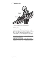
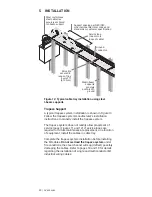
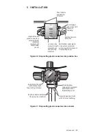
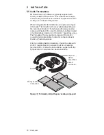
Figures 11 and 12 show two typical cable tray installation
methods using open ladder, trough-type tray. In Figure 11,
the cable tray is supported using a rod and channel trapeze
type system. In Figure 12, the tray is supported using steel
I-beams. Follow the cable tray manufacturer’s installation
instructions to install the tray.
Complete the cable tray installation before installing the
MI cables. Metallic cable tray systems must be electrically
continuous and effectively bonded as per the requirements
of the NEC / CEC or other national electrical codes and
standards.
Install cables so that the sheaths are in good electrical
contact with the tray. Do not overload the cable tray; follow
the loading requirements in the NEC / CEC or other national
electrical codes and standards when installing cables in
cable tray. Refer to pages 18 and 19 for details regarding
the installation of single and multiconductor MI industrial
wiring cables.
5 INSTALLATION
20 | nVent.com
Summary of Contents for pyrotenax Alloy 825
Page 1: ...MI Cable Industrial Wiring Installation Manual For Alloy 825 Sheath Cables ...
Page 4: ...iv nVent com ...
Page 46: ...42 nVent com ...
Page 47: ...nVent com 43 ...

