background image

Site Requirements

9

Space and water heating systems should be in accordance 

with the relevant recommendations of BS 5410: Part 1.

In a combined central heating and domestic hot water 

system, the hot water storage vessel must be of the 

indirect cylinder type to BS 1566: Part 1. The hot water 

storage vessel should be insulated with not less than 

75mm thick mineral fibre or its equivalent.

Cisterns and pipework should not be situated in areas 

which may be exposed by freezing conditions and should 

be insulated.

Draining taps must be located in accessible positions 

which permit the draining of the whole system, including  

the heat storage vessel. Draining taps should be at least 

1/2 in BSP nominal size and be in accordance with BS 

2879.

The appliance boiler section should be connected to 

cistern water supply, subject to a maximum head of 3 bar 

(30m), minimum of .1 bar (1m).

The heating system must be designed (and adjusted if 

necessary) to give temperature differential across the 

boiler at full output of 10-14°C. Where horizontal runs are 

used the pipes should rise upwards in the direction away 

from the appliance.

Circulating Pump

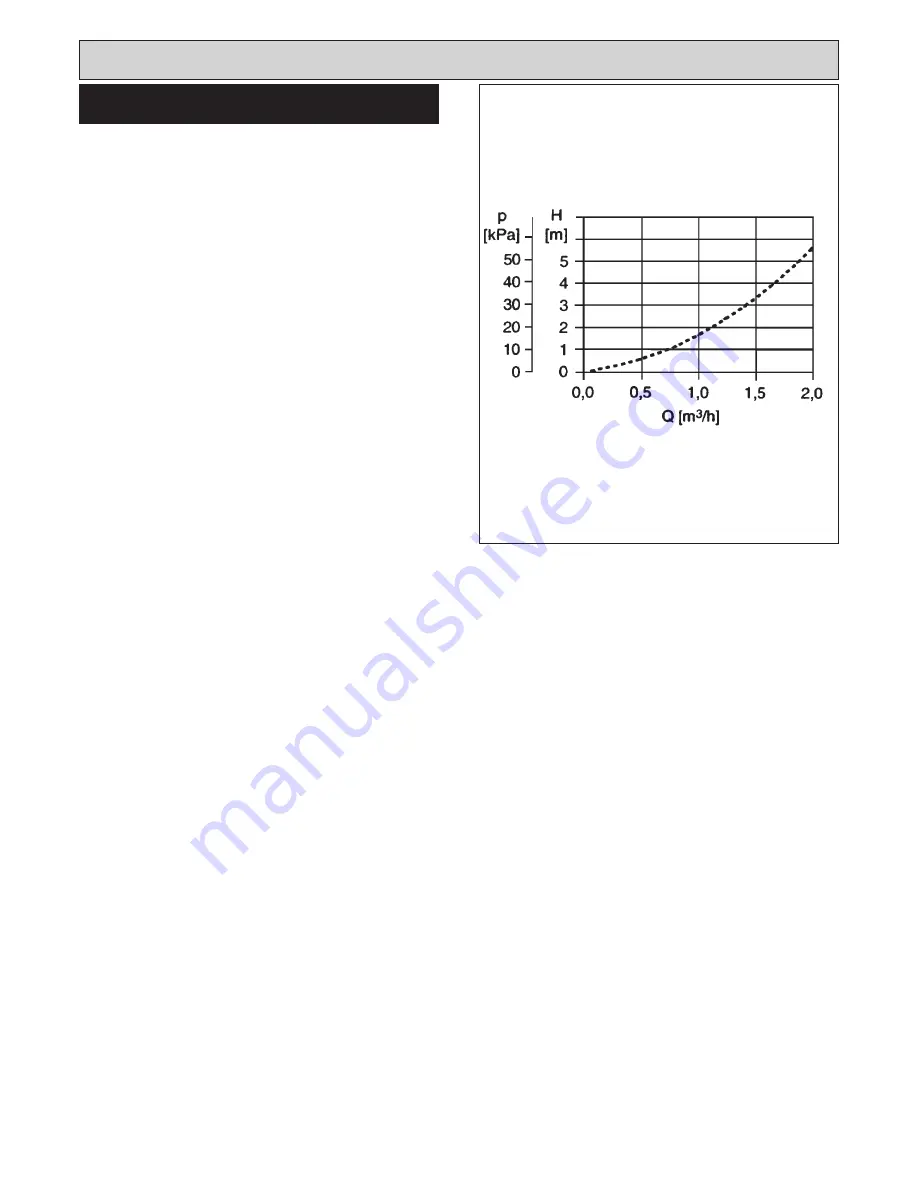
It is recommended that the selected pump be sized to suit 

the boiler pressure loss and therefore adequate to give 

the required temperature differential between the flow and 

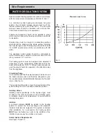
return. (See Fig. 4).

The pump should be able to meet the requirements of the 

system design and fit in a readily accessible position.

Isolating Valves

Isolating valves (preferably of the keyless type) must 

be fitted to the inlet and outlet of the circulating pump 

to facilitate service and replacement of pump without 

draining the system.

Inhibitor

A corrosion inhibitor 

MUST

 be added to the heating 

system to protect the heat exchanger and pipework. 

Inhibitor must also be replaced if the system is drained 

after installation. As a precaution the heating system 

MUST

 also be flushed out prior to the addition of the 

inhibitor to ensure any flux, debris is removed.

Sealed System Requirements

See Pages 18 and 19.

WATER CIRCULATION SYSTEM

Fig. 4

Pressure Loss Curve

Summary of Contents for Heatranger 480CD

Page 1: ... 514712 PLEASE READ THESE INSTRUCTIONS BEFORE USING THIS APPLIANCE REMEMBER when replacing a part on this appliance use only spare parts that you can be assured conform to the safety and performance specification that we required Do not use reconditioned or copy parts thay have not been clearly authorised by AGA ...

Page 2: ...SYSTEM SUITABILITY 11 ELECTRICAL CONNECTIONS 12 ELECTRICAL CHECKS 12 WIRING DIAGRAM 13 CONDENSATE TRAP 14 CONDENSATE PIPE 14 BALANCED FLUE INSTALLATION EXHAUST DUCT 15 TERMINAL GUARD 15 VENT PIPE 16 VENT PIPE GUARD 16 SEALED SYSTEM SEALED SYSTEM REQUIREMENTS 17 18 OPEN SYSTEM REQUIREMENTS 17 18 COMMISSIONING 17 18 COMMISSIONING ELECTRICAL INSTALLATION 19 WATER CIRCULATION SYSTEM 19 COMMISSIONING T...

Page 3: ...eted as being injurious to health and safety Glues and Sealants Exercise caution if these are still in liquid form use face mask and disposable gloves Glass Yarn Mineral Wool Insulation Pads Ceramic Fibre Maybe harmful if inhaled May be irritating to skin eyes nose and throat When handling avoid contact with skin or eyes Use disposable gloves face masks and eye protection After handling wash hands...

Page 4: ...t System 3 bar 30m Max Length 514mm Sealed System 3 bar 30m With Optional Extension1000mm Max Water Temp 82 C 3 C BOILER TOTAL COOKER 20 mbar 41 3 kW 26 7 kW 14 6 kW 23 4 kW Max Heat Inputs Gross Inlet Pressure Max Boiler Output 80 60 C net Min Boiler Output 80 60 C net 480CD NAT GAS G20 NOTE IT IS ADVISABLE TO CHECK THE ACTUAL SIZE WIDTH OF YOUR CUPBOARDS BEFORE FINALLY FIXING ANY KITCHEN UNITS S...

Page 5: ... for servicing the appliance In addition adequate clearance must be available at the front of the appliance to enable it to be operated and serviced Where the cooker is to stand in a recess or against a wall which is to be tiled in no circumstances should the tiles overlap the cooker top plate NOTE SMOKE SMELL EMITTED DURING INITIAL USAGE Some parts of the cooker have been coated with a light cove...

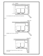
Page 6: ...Fig 2A Fig 2B 6 Fig 2C MINIMUM GAP ON RIGHT HAND SIDE GAP REQUIRED FOR SERVICING ON LEFT HAND SIDE WALL PROJECTING BEYOND THE FRONT OF THE APPLIANCE ...

Page 7: ...ncline so that any condensate formed in the flue drops back into the heat exchanger This is achieved by the design of the appliance the boiler flue should be angled when simply pushed into place This should result in the boiler flue being inclined and the cooker flue perfectly horizontal 4 Ensure that the guard is fitted centrally See Fig 16 5 The flue assembly shall be placed or shielded as to pr...

Page 8: ... so that it does not cause a nuisance and permits the dispersal of combustion products Consideration must be given as to the possible adverse affects of combustion noise on adjoining properties inherent with this type of product Fig 3 SEE FIG 3 The flue system must be installed in accordance with the regulations in force Terminal Position The minimum acceptable spacings from the terminal to obstru...

Page 9: ...ary to give temperature differential across the boiler at full output of 10 14 C Where horizontal runs are used the pipes should rise upwards in the direction away from the appliance Circulating Pump It is recommended that the selected pump be sized to suit the boiler pressure loss and therefore adequate to give the required temperature differential between the flow and return See Fig 4 The pump s...

Page 10: ...ust have the following minimum dimensions Between wall and LH side of appliance 150mm Between wall and RH side of appliance 10mm SHOULD THE WALL PROJECT BEYOND THE FRONT OF THE APPLIANCE WHEN IT MUST BE INCREASED TO 50mm SEE FIG 2A 2B 2c Above the raised insulating cover handle 60mm In addition the adequate clearance must be available at the front of the appliance to enable it to be operated and s...

Page 11: ...SUITABILITY THIS BOILER IS SUITABLE FOR FULLY PUMPED SYSTEMS ONLY For optimum operating conditions the heating system into which the boiler is installed should include a control system Such a system will include a time switch and a room thermostat and or cylinder thermostat The boiler should be controlled so that it is operated on demand only Operation of the system under control of the boiler the...

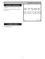
Page 12: ...onnected to the programmer or room stat The system pump and mains should be connected as shown in Fig 8 ELECTRICAL CHECKS Checks to ensure electrical safety should be carried out by a qualified engineer Installation Instructions 12 Fig 8 DESN 514865 ...

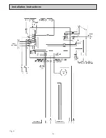
Page 13: ...Installation Instructions 13 Fig 9 ...

Page 14: ...Into an internal waste system with the end of the pipe into a gully below ground level but above the water line 2 Into an external waste system with the end of the pipe into a gully below ground level but above the water line 3 Into an internal soil and vent stack 4 Into an external purpose made soakaway As external condensate pipe runs may be susceptible to freezing during very cold weather it is...

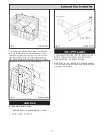
Page 15: ...the 60mm pipe ends to allow easier fitting into the couplings N B It may also be possible to use a high temperature grease to allow easier fitting To ensure the boiler flue has been fitted correctly into the boiler flue outlet remove the glass control facia and brackets behind The boiler elbow can then be adjusted if required and a correct fitting can also be checked of the flue The covering plate...

Page 16: ...ions VENT PIPE l Mark and cut pipe to length A Wall thickness B internal spacing 90mm l Locate vent pipe to appliance VENT PIPE GUARD A vent pipeguard is supplied with the cooker and must be fitted if the vent termination is less than 2 metres above ground level or subject to damage When fitted it must be positioned to provide a minimum of 50mm clearance from any part of the terminal and be centra...

Page 17: ...difficult by a remote automatic pressurisation and make up unit OPEN SYSTEM REQUIREMENTS If you are using an open system the pressure sensor on the flow pipe needs to be wired out of the system This is achieved by removing the RED link wire which connects between the pressure sensor and the overheat sensor The remaining wire on the pressure sensor should now be moved onto the spare terminal on the...

Page 18: ...Sealed System Fig 19 18 ...

Page 19: ...ntervals 3 Hand the Users Instructions to the User and demonstrate the correct operation of the appliance and system controls 4 Leave the Installation Servicing and Users instructions with the User 5 Gas Safety Show the user the procedure for isolating the appliance from the gas and electric supply As referred to in the Users Instructions Ref Gas Leak or Appliance Fault To light the burner turn th...

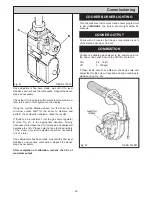
Page 20: ...decrease the CO2 Please note that due to the sensitivity of the screw only small adjustments will be necessary 1 8 of a turn Once adjustment has been made wait until the CO2 level stabilises and recheck combustion Repeat the above steps as necessary After completion of calibration recheck the CO2 at maximum output Fig 21 DESN 515016 Turn the cooker burner to mark H and ensure programmer is set to ...

Page 21: ...21 ...

Page 22: ...22 ...

Page 23: ...23 ...

Page 24: ...icy of continuous product improvement the Company reserves the right to change specifications and make modifications to the appliance described at any time Manufactured by AGA Rangemaster Station Road Ketley Telford Shropshire TF1 5AQ England Tel 0845 815 2020 www rayburn web co uk www agacookshop co uk ...

Reviews: