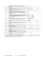
M7 GX Technical Manual
3
Raveon Technologies Corp.
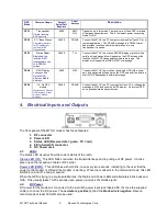
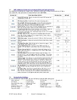
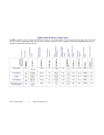
GPS
Mode
Common Usage
Default
Serial Port
Baudrate
Output
Message
Description
GPS 1
Transponder
Simple tracking,
AVL, security.
4800
RMC,
GLL
Transmit only in this mode. The receiver is off and GPS is turned
off between transmissions. This is the lowest-power consuming
mode. No RX.
GPS 2
PC / Base Station
Proprietary interface
for PC applications
that monitor M7
Transponders.
38400
PRAVE
Connect the
M7 GX
to a PC computer running RavTrack PC (or a
custom application), The PRAVE message is in NMEA format,
and provides location and status information for every
transponder it receives.
GPS 3
Marine Radar
Displaying the
location of M7
transponders on a
ship RADAR
screen.
38400
TLL
Connect the
M7 GX
to a marine RADAR display or plotter with a
serial port, and waypoints will appear on the GPS screen at the
location of all
M7 GX
transponders within radio range. The
display must support the NMEA 0183 TLL message.
GPS 4
GPS Display
Lowrance and
Garmin GPS
displays. Mobile
displays.
4800
WPL
Connect the
M7 GX
to a mobile or hand-held GPS with a serial
port, and waypoints will appear on the GPS screen at the location
of all
M7 GX
transponders within radio range.
GPS 5
-LX No GPS
module
Lowrance and Garmin
GPS displays. Radar
displays. Mobile
displays.
38400
PRAVE
Connect the
M7 GX
to a PC running
RavTrack PC
, or change the
message to WPL and use with a GPS display. No internal GPS,
so no positions/status transmissions.
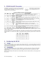
4. Electrical Inputs and Outputs
The front panel of the
M7 GX
modem has these features:
1. RF connector
2. Power LED
3. Status LED (Receive data = green, TX = red)
4. 9-Pin Serial I/O connector
5. DC Power Jack
4.1.
LEDs
The status LED visually show the current status of the radio.
Status LED (TX)
This LED blinks red when the transmitter keys and is putting out RF power. It blinks
green upon the reception of data or RF carrier.
Power LED (PWR)
This LED does a short blink, once every two seconds, indicating to the user that the
power to the modem is ON and the modem is working. When the modem is in the command mode, this LED
will blink on and off, once per second.
When the GPS is trying to acquire satellite lock, the Status and Power LEDs will alternately blink back and
forth. This usually takes 10-20 seconds upon power-up or loss of satellite signal.
4.2.
DC Power
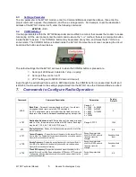
DC power for the modem is connected to the 2-pin DC power input jack labeled DC IN. Use the supplied
cable to connect the DC power. The
red wire is positive (+)
and the
black wire is negative.
Raveon
recommends at least 18 AWG wire be used.


