background image


39

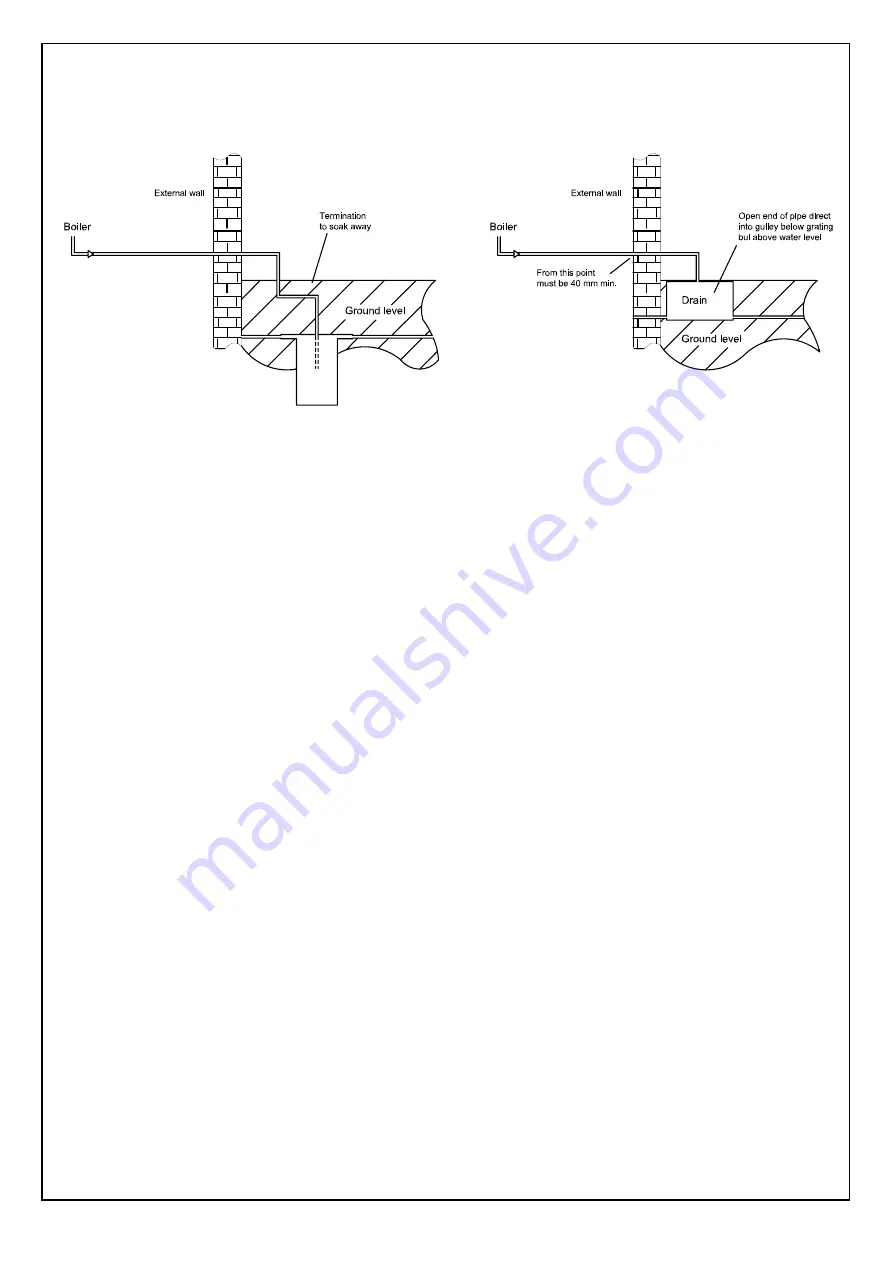
              3 - TERMINATION TO SOAK AWAY                              4 - TERMINATION TO DRAIN / GULLY                     

5.27


CONVERTING THE APPLIANCE 

                  TO DIFFERENT GAS TYPES 


         Boilers are factory set to work for use 

                  with Natural gas or LPG gas. This is 

clearly marked on the packaging  and 

                  boiler data badge.
                 

                  To convert a boiler from one gas to 
                  another this operation must be carried 
                  out by a qualified competent person, 
                  with all necessary equipment 

authorised by th

authorised by the manufacturer.

It will also be necessary to obtain a data badge 
conversion kit directly from The White Boiler 
Company. 

                  1 - Remove the case.
                  2 - Check  gas mains pressure at the  gas  
                       valve test nipple upstream (fig.35)
                       with boiler operating (sect.6.8).
                  3 - Adjust fan speed as sect.3             
                       (technical data). 
                  4 - Measure the level of CO2 as in section 

as in section 

                       6.9 and table 10,  and adjust to correct 

                       6.9 and table 10,  and adjust to correct 
                       data settings information.

                       data settings information.
                  5 - Affix new data badge.
                  6 - Replace in reverse order.

5.28 ELECTRICAL 

CONNECTIONS

              IMPORTANT:


              Electricity supply must be as specified in 

clause (sect. 4.22).

            - When controls external to the appliance are 

required, design of the external electrical 
circuits should be undertaken by a 

              competent person. In accordance with the 

IEE wiring regulations.

 It is essential that all external controls 
 are VOLT FREE.

 Factory fitted internal wiring must not be 
 disturbed when wiring external controls.

 - To gain access to the electrical box remove 
   the front panel of the case as described in 
   clauses sect. 8.2.

8.2.

   You can slide towards the top the

   You can slide towards the top the
   instrument panel box and push the retaining 

   instrument panel box and push the retaining 
   latches and remove the instrument panel 

   latches and remove the instrument panel 
   (sect. 8.24).

   (sect. 8.24).
-  Heat resistant flexible cable is fitted 

-  Heat resistant flexible cable is fitted 
   between the isolator and the terminal block 

   between the isolator and the terminal block 
   which is a 3 core cable 

   which is a 3 core cable of 0.75 mm

2

 (24x0,2 

   mm) to BS 6500.

    Make sure all wires to the appliance are 
    routed away from sharp edges and hot 
    surfaces.

 The cable must be fastened with its cord 
 anchorage and connected so that should 
 the cable slip from the anchorage the 
 current carrying conductors become taut 
 before the earthing conductor. Securely 
 tighten all terminal screws and arrange 
 the cable with slack between the cord 
 anchorage and the terminal block. 

WARNING: 
If the supply cord is damaged, it must be 
replaced by a service engineer (supply 
cord available from The White Boiler 
Company).


5.29     OUTDOOR SENSOR 

               For use, consult Outdoor Sensor
               instructions.  


 Fig. 33

 
 Fig. 34

Summary of Contents for White Boiler WH 80

Page 1: ...RLEY LEEDS LS27 9ET TEL 0113 252 7007 FAX 0113 238 0229 Website www ravenheat co uk E mail sales ravenheat co uk Instructions for Use Installation and Servicing To be left with the user WH 80 T Natural Gas G20 I 2H II 2H3 G C No 47 506 05 LPG G30 31 I 2H II 2H3 G C No 47 506 06 WH 90 T Natural Gas G20 I 2H II 2H3 G C No 47 506 07 LPG G30 31 I 2H II 2H3 G C No 47 506 08 1312 THE WHITE BOILER COMPAN...

Page 2: ...2 ...

Page 3: ...eat transfer to domestic hot water supply Stainless steel plate heat exchanger for super high heat transfer to domestic hot water supply Built in frost protection Built in frost protection Printed circuit board designed to connect to room stat and or timer frost stat Printed circuit board designed to connect to room stat and or timer frost stat Aesthetically pleasing panels and controls Aesthetica...

Page 4: ... natural gas 14 5 17 Exhaust suction system with two 35 3 1 Technical data WH 80 T LPG 15 separate pipes through a single 3 2 Technical data WH 90 T natural gas 16 vertical wall 3 3 Technical data WH 90 T LPG 17 5 18 Installation instructions for 80 125 36 concentric flue system 4 General requirements 18 5 19 Assemble boiler 37 4 1 Safety 18 5 20 Fitting valve pack 37 Gas safety Installation and u...

Page 5: ...t 47 exchanger 8 9 To remove replace expansion 48 vessel 8 10 To remove replace gas valve 48 8 11 To remove replace plate heat 48 exchanger 8 12 To remove replace the water 48 pressure transducer 8 13 To remove replace diverter valve 49 motor 8 14 To remove replace C H diverter 49 valve 8 15 To remove replace D H W diverter 49 valve mechanism 8 16 To remove replace pump 49 8 17 To remove replace a...

Page 6: ...ANCE CHECKING THE SYSTEM YOUR APPLIANCE CHECKING THE SYSTEM PRESSURE PRESSURE Before lighting the appliance check that the Central Before lighting the appliance check that the Central Heating system pressure is not less than 1 bar If it Heating system pressure is not less than 1 bar If it is below this it will be necessary to re pressurise the is below this it will be necessary to re pressurise th...

Page 7: ...t temperature when the digital display is in hot water or domestic set point temperature Press also to show the boiler values or to show the options program when the digital display is in menu setting 5 Press to set the Central Heating Temperature required when in winter mode Press the arrow up or the arrow down buttons to increase or decrease the temperature 6 Press to set the Domestic Hot Water ...

Page 8: ...hursday 4 Thursday 5 Friday 5 Friday 6 Saturday 6 Saturday 7 Sunday 7 Sunday 2 Time time clock version only 2 Time time clock version only 3 Central Heating when the appliance 3 Central Heating when the appliance is in central heating mode icon 3 will be is in central heating mode icon 3 will be flashing flashing 4 Auto time clock version only when the 4 Auto time clock version only when the digit...

Page 9: ...his group will remain at the default time For example setting Mon Sat For example setting Mon Sat will change all these days but Sunday will remain the same as table one unless changed individually The programmed times will only be activated when the boiler is in winter mode section 1 4 key 1 and also set in auto mode section 1 4 key 7 If you wish to override these times press the timer mode butto...

Page 10: ...elief valve 12 Water pressure transducer 13 CHreturn 14 Controlboard 15 Circulation pump 16 Automaticairvent 17 Condensatedrain 18 Expansionvessel 19 Mainheatexchanger 20 Sparkelectrode 21 Sensingelectrode 22 Fluetemperaturesensor 23 Sparkigniter 24 Fan 25 Burner 26 Manualairvent 27 Overheatcutoffthermostat 28 CHflowsensor 29 CH return sensor 2 0 GENERAL LAYOUT Fig 3 Fig 3 ...

Page 11: ...11 Spark electrode 12 Sensor electrode 13 Fan 14 Flue temperature temperature sensor 15 Expansion vessel 16 Automatic air vent 17 Circulation pump 18 Water pressure transducer 19 Safetypressurereliefvalve 20 Diverter valve motor 21 Plate heat exchanger 22 DHW sensor 23 Gasvalve 24 Gasservicecock 25 CHcompressionballvalves 26 DHWcompressionballvalves 2 1 OPERATING SCHEME Fig 4 Fig 4 ...

Page 12: ...eing for With the summer position only being for domestic hot water domestic hot water The winter position being for central heating The winter position being for central heating with domestic hot water priority with domestic hot water priority 2 3 2 3 DESCRIPTION OF CONTROL SYSTEM DESCRIPTION OF CONTROL SYSTEM AND SEQUENCE OF OPERATION AND SEQUENCE OF OPERATION 2 4 Domestic hot water mode 2 4 Dom...

Page 13: ...tion by pressing the Select the summer position by pressing the summer winter button The boiler functions summer winter button The boiler functions like an automatic gas hot water heater like an automatic gas hot water heater When D H W is no longer required the When D H W is no longer required the burner and pump and fan will immediately burner and pump and fan will immediately turn off turn off ...

Page 14: ...m compression valve SAFETY DISCHARGE C H 15 mm copper pipe CONDENSATION DRAIN 3 4 21 5 mm push fit over flow MAX COLD WATER CAPACITY WITHOUT ADDITIONAL EXPANSION VESSEL 110 LITRE SEALED WATER SYSTEM C H MAX PRESSURE PHS 2 5 bar MINIMUM WORKING PRESSURE 0 5 bar 7 LITRES EXPANSION VESSEL PRE CHARGE PRESSURE 0 5 bar CENTRAL HEATING OPERATING TEMPERATURE MAX 80 C min 35 C DESIGN FLOW RATE 1383 I h 20 ...

Page 15: ...compression isolating valve OUTLET CONNECTION D H W 15 mm compression valve SAFETY DISCHARGE C H 15 mm copper pipe CONDENSATION DRAIN 3 4 21 5 mm push fit over flow MAX COLD WATER CAPACITY WITHOUT ADDITIONAL EXPANSION VESSEL 110 LITRE SEALED WATER SYSTEM C H MAX PRESSURE PHS 2 5 bar MINIMUM WORKING PRESSURE 0 5 bar 7 LITRES EXPANSION VESSEL PRE CHARGE PRESSURE 0 5 bar CENTRAL HEATING OPERATING TEM...

Page 16: ... mm compression valve SAFETY DISCHARGE C H 15 mm copper pipe CONDENSATION DRAIN 3 4 21 5 mm push fit over flow MAX COLD WATER CAPACITY WITHOUT ADDITIONAL EXPANSION VESSEL 110 LITRE SEALED WATER SYSTEM C H MAX PRESSURE PHS 2 5 bar MINIMUM WORKING PRESSURE 0 5 bar 7 LITRES EXPANSION VESSEL PRE CHARGE PRESSURE 0 5 bar CENTRAL HEATING OPERATING TEMPERATURE MAX 80 C min 35 C DESIGN FLOW RATE 1811 I h 2...

Page 17: ...NNECTION D H W 15 mm compression valve SAFETY DISCHARGE C H 15 mm copper pipe CONDENSATION DRAIN 3 4 21 5 mm push fit over flow MAX COLD WATER CAPACITY WITHOUT ADDITIONAL EXPANSION VESSEL 110 LITRE SEALED WATER SYSTEM C H MAX PRESSURE PHS 2 5 bar MINIMUM WORKING PRESSURE 0 5 bar 7 LITRES EXPANSION VESSEL PRE CHARGE PRESSURE 0 5 bar CENTRAL HEATING OPERATING TEMPERATURE MAX 80 C min 35 C DESIGN FLO...

Page 18: ...ster www gassaferegister co uk Failure to install appliances correctly could lead to prosecution It is in your own interest and that of your safety to ensure the law is complied with Check the boiler and flue is the correct type for installation undertaken The installation of the boiler MUST be in The installation of the boiler MUST be in accordance with the latest I E E BS 7671 accordance with th...

Page 19: ...ance is installed in a room containing a bath or shower any electrical switch or appliance control utilising mains electricity should be situated so that it cannot be touched by a person using a bath or shower A compartment when used to enclose the combination boiler MUST be designed and constructed specifically for this purpose An existing cupboard or compartment may be used provided it is modifi...

Page 20: ...dations of BS 5440 Part 1 IMPORTANT NOTES For greater flue lengths see alternative flue instructions Flue must be positioned in a place not likely to cause a nuisance from pluming IMPORTANT NOTICE If the flue terminates below a balcony above the ground above a flat roof to which people have access then a suitable terminal guard must be fitted if less than 2 meters high less than 2 meters high PRO1...

Page 21: ...21 4 10 FLUE TERMINAL POSITION ...

Page 22: ...ould have a gradient to ensure air is carried naturally to air release to ensure air is carried naturally to air release points and water flows naturally to drain points and water flows naturally to drain taps It should be ensured as far as possible taps It should be ensured as far as possible that the appliance s heat exchanger is not a that the appliance s heat exchanger is not a natural collect...

Page 23: ...nsion see table 4 and add additional sealed expansion capacity as additional sealed expansion capacity as appropriate Fig 7 In general modern appropriate Fig 7 In general modern systems below 7 lts should not present any systems below 7 lts should not present any problem problem 4 15 4 15 MAINS WATER FEED CENTRAL HEATING MAINS WATER FEED CENTRAL HEATING There must be no direct connection to the Th...

Page 24: ...guarantee and invalidate the appliance guarantee and contravene the Building Regulations contravene the Building Regulations It is recommended that you fit a primary It is recommended that you fit a primary water cleanser to the system We water cleanser to the system We recommend fitting a filter that will help recommend fitting a filter that will help remove both magnetite and non magnetic remove...

Page 25: ...acent to the appliance except where the appliance is installed in a bathroom The current electrical IEE Wiring regulations must be followed in GB 5 INSTALLATION 5 1 WARNING It is MOST IMPORTANT that this appliance is installed in a HORIZONTAL POSITION with the flue air duct passing through the wall Make sure the flue is at a 1 5 incline rising from the boiler with 50 mm Flue terminal diagram state...

Page 26: ...LUE KIT BOX CONTAINING Fig 10 57 Elbow header 59 Rubber seal Ø 60 56 Rubber seal Ø 100 60 Fumes sample point 61 Flue exhaust duct 62 Air intake duct 69 Air sample point 127 Terminal Rubber wall seal Fig 11 Fig 10 WARNING With horizontal concentric flue the maximum flue the maximum flue length is 8 metres flue length is 8 metres duct extension can be used with the standard flue see table 5 FLUE EXT...

Page 27: ...Fig 12a FLUE EXHAUST DEFLECTION BEND Fig 12a Flue exhaust deflection bend are also available These come in both 45 and 90 degree versions These bends fit directly onto the flue exhaust terminal to deflect the flue gas plume in an upward or sideways direction Although they are not substitute for a plume kit they can be considered useful where condensate pluming is causing a nuisance or can be used ...

Page 28: ...to locate inner and outer flue correctly ensuring a good seal is made with O rings Tighten the a good seal is made with O rings Tighten the two screws on the flue flange to secure the two screws on the flue flange to secure the elbow header in place elbow header in place Fit the terminal rubber wall seal and if Fit the terminal rubber wall seal and if necessary terminal guard necessary terminal gu...

Page 29: ...installed with the widened end of the air be installed with the widened end of the air intake pipe and the tapered end of the flue intake pipe and the tapered end of the flue pipe aimed towards the exhaust terminal pipe aimed towards the exhaust terminal NOTE The position of the appliance must provide minimum side clearances of 5mm as the side panels do not require removing for servicing However i...

Page 30: ...cket is available from The White Boiler Company and should be used to support the flue length at least every one metre preferably at each joint this bracket should be secured to wall and flue duct SIDE FLUE OUTLET Fig 14 NOTE The position of the appliance must provide minimum side clearances of 5mm as the side panels do not require removing for servicing However if the option is preferred to remov...

Page 31: ...sion 64 Flue exhaust duct extension 65 Flue manifold rubber seal 66 Securing screw 67 Flue temperature sensor 69 Air sample point 127 Terminal Rubber wall seal Fig 16 IN LINE FLUE BEND Measure the distance between the flue bends or the flue terminal assembly The measurements should be taken from the outer edge of the flue and bend fig 18 5 9 COMPLETING HORIZONTAL FLUE INSTALLATION Ensure the flue ...

Page 32: ...he centre line is vertical and that the flue centre line is virtually below the point at which the flue will exit the roof Ensure that the maximum permissible flue permissible flue length is not exceeded fig 20 and see table 5 length is not exceeded fig 20 and see table 5 Mark the two wall fixing bolt holes Mark the two wall fixing bolt holes Detach the template from the wall Detach the template f...

Page 33: ...inal assembly through the flashing slate from the outside Lift the boiler on the wall locating onto the top two fixing bolts Tighten the two bolts using a spanner to secure to the wall Measure the vertical distance between the top of the flue and the bottom of the flue terminal assembly fig 21 The measurements should be taken from the outer diameter of the flue NOTE Where this length does not matc...

Page 34: ... is located into the flue manifold and lubricate the internal part of the seal before assembly the internal part of the seal before assembly Locate the header gasket on the twin flue Locate the header gasket on the twin flue header and push into the flue adaptor making header and push into the flue adaptor making sure that the inner plastic exhaust sure that the inner plastic exhaust locates firml...

Page 35: ...per metre Exhaust suction system with two separate pipes through a single vertical wall fig 26 Maximum distance D L L1 37 metre Minimum distance D L L1 1 metre Min distance between pipe 50 mm IMPORTANT NOTICE Inlet and exhaust terminals must never be installed on opposite walls of the building PrEN 483 If the flue terminates less than 2 m above a balcony above the ground or above a flat roof to wh...

Page 36: ...7 Part No Description PR5094110A Straight flue header sample point 60 100 PRO110300 Flue Extension 80 125 L1000 RID110050 125 80 to 100 60 Flue reducer CUR110250 45 flue bend 80 125 CUR110300 90 elbow flue bend 80 125 TER010050 Horizontal Flue Terminal 80 125 TER110200 Vertical Flue Terminal 80 125 TEG060050 Flashing sleeve slate IMPORTANT See fig 6 for terminal clearances See fig 6 for terminal c...

Page 37: ...G CONNECTION Fig 29 Before any central heating connections are made to the boiler all system valves should be opened and the system thoroughly flushed out with cold water Connect the central heating return pipe to the isolating cock Connect the central heating flow pipe to the isolating cock marked CHF Pipe dimensions and positions are marked on template supplied fig 30 5 23 DOMESTIC HOT WATER CON...

Page 38: ...y from the boiler Condensate should if possible be discharged into the household internal drainage system If this is not practicable discharge can be allowed into the external household drains or a purpose designed soak away It is recommended that any external condensate drain pipe is insulated and also must be of 40 mm 1 1 2 diameter through the outside wall to prevent freezing in adverse weather...

Page 39: ...th the IEE wiring regulations It is essential that all external controls are VOLT FREE Factory fitted internal wiring must not be disturbed when wiring external controls To gain access to the electrical box remove the front panel of the case as described in clauses sect 8 2 8 2 You can slide towards the top the You can slide towards the top the instrument panel box and push the retaining instrumen...

Page 40: ...e P button once again to return to the main button once again to return to the main screen screen Then turn off the filling points stopcock Inspect the system for water soundness and remedy any leaks discovered 6 4 SETTING THE HEATING SYSTEM DESIGN PRESSURE The design pressure must be a min 1 bar and max 1 5 bar These figures are read on the digital display by pressing the P button The actual read...

Page 41: ...on fluid test for gas tightness With leak detection fluid test for gas tightness of all gas components and joints of all gas components and joints IMPORTANT IMPORTANT The Gas Valve Throttle adjuster is required The Gas Valve Throttle adjuster is required to be sealed with tamper proof paint after to be sealed with tamper proof paint after adjustment fig 35 adjustment fig 35 6 9 6 9 COMBUSTION CHEC...

Page 42: ...re flow regulator should be fitted on the cold water supply to the appliance Slowly close the draw off tap to reduce the flow rate to the min approx 2 8 litre min Select a different temperature for D H W to ensure it operates at its various setting Close the draw off tap still further The burner should stop when the rate falls below about 2 8 litres min 0 61 gals min 6 13 KEEP HOT The boiler comes...

Page 43: ...u seconds to enter in menu Use arrow up and arrow down buttons Use arrow up and arrow down buttons item 3 and 4 fig 1 to select BOIL item 3 and 4 fig 1 to select BOIL Press enter and reset buttons item 2 Press enter and reset buttons item 2 and 3 fig 1 together and enter button and 3 fig 1 together and enter button again again Use arrow up and arrow down buttons Use arrow up and arrow down buttons...

Page 44: ... and be calibrated in accordance with the analyser manufacturers requirements Competence can be demonstrated by satisfactory completion of th satisfactory completion of the CPA1 ACS assessment which covers the use of electronic portable combustion gas analysers in accordance with BS 7967 Parts 1 to 4 7 1 BOILER FROST PROTECTION The appliance has a built in frost protection device that protects the...

Page 45: ...do not use excessive force Examine the spark and sensing electrodes for any mechanical damage Clean away any debris and check the spark and sensing gap Examine flue duct and flue manifold and ensure that there is no obstruction Examine the gasket at the entry into the flue manifold It is essential that a good seal is made at the outlet to the flue manifold renew this gasket if there is any sign of...

Page 46: ...in reverse order always fitting a Replace in reverse order always fitting a new gasket new gasket 8 3 TO REMOVE LEFT AND RIGHT PANELS Fig 40 Remove front panel fig 39 Remove front panel fig 39 Unscrew the four screw to the bottom Unscrew the four screw to the bottom panel panel Unscrew the two screws to the side panel Unscrew the two screws to the side panel rotate 48 mm and unhook rotate 48 mm an...

Page 47: ...m the fan the fan U Unscrew the screws to the burner cover and remove the cover with the fan To remove the burner unscrew the screws in the lower cover side Replace in reverse order always fitting a new gasket Fig 43 8 8 TO REMOVE REPLACE THE MAIN HEAT EXCHANGER Remove front and bottom panels fig 39 40 Drain the boiler CH circuit and drain the DHW circuit Follow the instructions to Follow the inst...

Page 48: ...if necessary see section 6 9 8 11 TO REMOVE REPLACE PLATE HEAT EXCHANGER Fig 46 Remove front and bottom panels fig 39 40 Remove the panel control box sect 8 23 Close off the on off valves for CH circuit and DHW circuit and drain the boiler and drain hot water from the lowest hot water tap Unscrew the two al Unscrew the two allen screws that connect the DHW heat exchanger and pull it out from the b...

Page 49: ...ew the nut that fastens the pump to Unscrew the nut that fastens the pump to the CH pipe and remove the pump and the CH pipe and remove the pump and remove the securing clip at the pump remove the securing clip at the pump manifold manifold Replace in reverse order Replace in reverse order NOTE NOTE Always use new O ring Always use new O ring 8 17 TO REMOVE REPLACE AUTOMATIC AIR VENT Fig 48 Remove...

Page 50: ...LACE C H FLOW AND RETURN SENSORS Fig 49 RETURN SENSORS Fig 49 Remove front panel fig 39 Detach the wire connector and remove Detach the wire connector and remove the retaining cli the retaining clip sensor from the pipe NOTE When reconnecting ensure the correct wires go to the relevant sensor the polarity on each one is unimportant 8 21 TO REMOVE REPLACE FLUE SENSOR Fig 3 item 22 Remove f front pa...

Page 51: ...D Fig 55 BOARD Fig 55 Remove front panel fig 39 Remove front panel fig 39 Remove the instrument panel sect Remove the instrument panel sect 8 24 8 24 Detach all connectors from control board Detach all connectors from control board unscrew the four screws and lift up unscrew the four screws and lift up Replace in reverse order fig 55 Replace in reverse order fig 55 8 26 TO REMOVE REPLACE DIGITAL 8...

Page 52: ... supply has been purged of air The heating system pressure is at least 1 bar min to 1 5 bar max select winter position on the digital display and set the central heating temperature to maximum sect 1 5 Ensure external controls are calling for heat room thermostat digital clock and check the following appliance operations 52 ...

Page 53: ...position on the digital display and setting see section 9 and after selecting the summer position on the digital display and setting the domestic hot water temperature to maximum the domestic hot water temperature to maximum sect 1 5 Open the domestic hot tap and check the following appliance operations ...

Page 54: ...10 ELECTRICAL SYSTEM DIAGRAM 54 Fig 61 ...

Page 55: ...55 11 SPARE PARTS Fig 62 ...

Page 56: ...0 Diverter valve by pass 21 FOR150050 Diverter valve motor clip 22 MOT150050 Diverter valve motor 23 5018030 3 4 gasket GUA010250 24 TUB150150 Gas valve inlet pipe 25 TUB150070 Flow pipe 26 SON110100 C H flow and return sensors SON110150 27 ORI150100 Primary heat exchanger O ring 28 FOR150050 Primary heat exchanger clip 29 TER080050 Overheat thermostat TER060150 30 VAL150200 Manual air vent 31 TUB...

Page 57: ...0050 WH 80 burner 50 1 BRU150100 WH 90 burner 51 FLA110050 Flue flange FLA110052 52 GUA110350 Flue flange gasket 53 GUA110250 Flue manifold washer GUA130050 54 TER130050 Temperature flue sensor 55 GEN150100 Spark igniter 56 COL150050 Flue exhaust manifold 57 SCA150050 WH 80 main heat exchanger 57 1 SCA150100 WH 90 main heat exchanger 58 VAS150050 Expansion vessel 59 GUA050050 3 8 gasket GUA060111 ...

Page 58: ... concentric flue 80 125 see sect 5 18 Part No Description PR5094110A Straight flue header sample point 60 10 PRO110300 Flue Extension 80 125 L1000 RID110050 125 80 to 100 60 Flue reducer CUR110250 45 bend 80 125 CUR110300 90 elbow bend 80 125 TER010050 Horizontal Flue Terminal 80 125 TER110200 Vertical Flue Terminal 80 125 TEG060050 Flashing sleeve slate Accessories eccentric flue 80 80 see sect 5...

Page 59: ......

Page 60: ...tists Way Morley Leeds LS27 9ET Telephone 0113 252 7007 Fax 0113 238 0229 Website www ravenheat co uk E mail sales ravenheat co uk Ravenheat reserves the right to make changes and improvements in our products which may affect the accuracy of the information contained in this leaflet ...

Page 61: ...trols Central heating return temp measure and record Temperature control to heating 12 For combination boilers only Temperature control to hot water 12 Scale reducer 25 Heating zone valves n a Hot water mode Auto by pass 22 Max operating burner pressure measure and record Boiler interlock 22 Max operating water pressure measure and record Cold water inlet temp measure and record For all boilers Ho...

Page 62: ...61 ...

Page 63: ...62 ...

Page 64: ... commissioning checNlist completed in full 7o instigate the boiler guarantee the boiler needs to be registered with the manufacturer within one month of the installation 7o maintain the boiler guarantee it is essential that the boiler is serYiced annually by a as 6afe registered engineer who has been trained on the boiler installed 7he serYice details should be recorded on the enchmarN 6erYice Int...

Page 65: ...64 FLOWCHART FOR CO LEVEL AND COMBUSTION RATIO CHECK ON COMMISSIONING A CONDENSING BOILER ...

Page 66: ...65 12 1 ANALYSER CHECK LIST ...

Page 67: ... required oiler interlocN 3roYided ALL SYSTEMS 7he system has been Àushed and cleaned in accordance with 6 and boiler manufacturer s instructions Yes hat system cleaner was used hat inhibitor was used 4uantity litres Has a primary water system lter been installed Yes 1o CENTRAL HEATING MODE measure and record as rate mñ hr OR ftñ hr urner operating pressure if applicable mbar OR as inlet pressure ...

Page 68: ... as safe register 1o Record t ma rate CO ppm AND CO t min rate here 3ossible CO ppm AND CO Comments 6ignature SERVICE 04 ate ngineer name Company name Telephone 1o as safe register 1o Record t ma rate CO ppm AND CO t min rate here 3ossible CO ppm AND CO Comments 6ignature SERVICE 05 ate ngineer name Company name Telephone 1o as safe register 1o Record t ma rate CO ppm AND CO t min rate here 3ossib...

Reviews: