background image

OPERATING

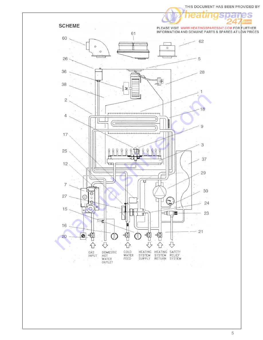
Fig. 2

KEY

1 - Heat exchanger

2 - Heat exchanger for D.H.W. water
3 - Burner
4 - Pilot burner
5 - Air restriction ring
7 - Electronic ignition
9 - Ignition electrode

12 - Modulating gas valve
15 - Heating control
16 - Hot water control

17 - Low water pressure switch
18 - Overheat cut-off thermostat

20 - Gas service cock
21 - Compression ball valves
23 - Safety relief system
24 - Three way valve
25 - Flow regulator
26 - Auto air vent valve
27 - D.H.W. pressure switch giving priority
28 - Air pressure switch

29 - Circulating pump
30 - Water pressure gauge
36 - Fan
37 - Expansion tank
38 - Sealed chamber
60 - Elbow header
61 - Twin header
62 - Straight header

Summary of Contents for RSF 84E

Page 1: ...om Water Fitting Byelaws Scheme WITH TIMER RSF 84ET G C No 47 581 28A RSF 1OOET G C No 47 581 26A NATURAL GAS G 20 AND PROPANE G 31 INSTALLATION AND SERVICING INSTRUCTIONS TO BE LEFT WITH USER Technic...

Page 2: ...lity diverter valve with ethylene propylene diaphragm permitting primary fluid cir culation in the boiler during D H W supply This gives maximum heat exchange improved effi ciency and exceptionally si...

Page 3: ...changer 3 Burner 4 Pilot burner 7 Ignition board 9 Ignition electrode 11 Frame 12 Modulating gas valve 15 Heating control 16 Hot water control 4 17 D H W sensor 18 Water pressure switch heating circui...

Page 4: ...t water control 17 Low water pressure switch 18 Overheat cut off thermostat 20 Gas service cock 21 Compression ball valves 23 Safety relief system 24 Three way valve 25 Flow regulator 26 Auto air vent...

Page 5: ...o rest mode the main burner is shut down along with the pilot burner The pump and fan are also 2 2 6 2 2 7 2 2 8 2 2 9 2 3 2 3 1 2 3 2 2 3 3 2 3 4 2 3 5 2 3 6 2 3 7 switched off the pressure switch re...

Page 6: ...e boil er automatically returns to the central heat ing mode Switch 33 in the summer position The boiler functions like an automatic gas hot OVERALL DIMENSION AVAILABLE PUMP HEAD 3 1 SAFETY DEVICE In...

Page 7: ...ve RETURN CONNECTION C H 22 mm compression isolating valve INLET CONNECTION D H W 15 mm compression isolating valve OUTLET CONNECTION D H W 15 mm compression MAXIMUM PERMISSIBLE COLD WATER CAPACITY WI...

Page 8: ...io 22 mm compressio 15 m 15m 4 9 in w g 1 96 in w g 0 56 in w g n isolating valve n isolating valve m compression isolating valve m compression MAXIMUM PERMISSIBLE COLD WATER CAPACITY WITHOUT ADDITION...

Page 9: ...g valve RETURN CONNECTION C H 22 mm compression isolating valve INLET CONNECTION D H W 15 mm compression isolating valve OUTLET CONNECTION D H W 15 mm compression MAXIMUM PERMISSIBLE COLD WATER CAPACI...

Page 10: ...lve RETURN CONNECTION C H 22 mm compression isolating valve INLET CONNECTION D H W 15 mm compression isolating valve OUTLET CONNECTION D H W 15 mm compression MAXIMUM PERMISSIBLE COLD WATER CAPACITY W...

Page 11: ...rposes 2nd Family Gases BS 544O 1 Flues for gas appliances of rated input not exceeding 60 kW BS 5440 2 Ventilation for gas appliances of rated input not exceeding 60 kW Health Safety Document No 635...

Page 12: ...d accordingly 2 M above a balcony above the ground or above a Samples of the RSF 84E 84ET RSF flat roof to which people have access then a suitable 1OOE 1OOET combination boilers have terminal guard m...

Page 13: ...y Where installed in a cupboard or compart ment ventilation is not required 4 8 4 8 1 WATER CIRCULATION central heating Detailed recommendation are given in BS 6798 1987 5449 1990 for smallbore and mi...

Page 14: ...r cold water distribut ing pipe The unit may remain permanently connected to the heating system to provide limited automatic water make up Mains topping up method Fig 9 Here the temporary connection i...

Page 15: ...ent device is installed in sel sizing is given in Table 5 the mains Reference should be made to British Gas The water hardness can be determined by Publications Material and Installation using the sta...

Page 16: ...WARNING 5 1 1 It is MOST IMPORTANT that this appliance is installed in a VERTICAL POSITION with the flue air duct passing through the wall in a HORIZONTAL PLANE A minor deviation from the horizontal i...

Page 17: ...ons 59 Rubber seal 0 60 63 Air intake duct extension 64 Flue exhaust duct extension 65 Pipe centering spring STRAIGHT HEADER BOX CONTAINING Fig 13 55 Rubber seal 0 100 57 Straight header supplied as a...

Page 18: ...Fig 19 Carefully slide the front panel a few mil limetres up towards the top of the appli ance until it is free from its slot and then lift off Fig 20 5 4 2 Unscrew the 2 screws that fasten the lower...

Page 19: ...ive tape to attach the template to the wall making sure that the centre line is vertical Mark the four boiler fastening holes on the wall as well as the centre of the flue duct Detach the template fro...

Page 20: ...gles to a length equal to W 264 mm Insert from cut end Reassemble the two tubes Insert centering spring 65 Must be de burred Reassemble together inner and outer flue duct insert centering spring Fig 3...

Page 21: ...t be shortened this must be done from the straight end and not from the widened or tapered end To measure the pipeline properly all compo nents must be assembled and total length measured before cutti...

Page 22: ...rest side wall is not less than MEASUREMENT IN TABLE 6 Mark the four boiler securing holes on the wall and extend the axis of the flue duct hole to the side wall ensuring it is horizontal Trace the ce...

Page 23: ...37 Extension kits are available on order for flue extension of up to 2 5 metres total length Fig 31 39B For further details see sect 5 5 10 5 7 12 1 VERTICAL FLUE OPTIONS The vertical flue kit is inte...

Page 24: ...mplate from the wall Use a 10 mm dia drill to make the 4 boil er securing holes Insert plastic expan sion plugs Fig 29 Screw in the two upper coach bolts leav ing them about 10 mm out from the wall to...

Page 25: ...pipe to the isolating cock marked CHF Pipe dimension s and position are marked on template supplied and Fig 49A 5 11 DOMESTIC HOT WATER Fig 46 5 11 1 The domestic hot water circuit does not need a sa...

Page 26: ...RAMMABLE TIME CLOCK Instructions for use Consult User s Guide Fig 49 A 6 1 Each boiler has been through a rigorous operational procedure at our factory and should not require any further adjustment If...

Page 27: ...system above the base of the appliance up to a max of 1 5 bar N B The safety valve is set to lift a 3 bars 30 mt 42 5 psig To lower the system pressure to the required value remove drain point Fig 93...

Page 28: ...on fluid test for gas soundness of all gas components and joints See paragraph 6 14 for regulating the heating circuit thermostat Check gas mains pressure Fig 52 Fit a gas pressure gauge on pressure i...

Page 29: ...be about 20 mm long Fig 52B and envelop the spark electrode tip 6 10 ADJUSTING MINIMUM AND MAXIMUM PRESSURE Fig 51 SIT HONEYWELL GAS VALVE Remove cap covering modulator to gas valve Detach one of the...

Page 30: ...to operate the differential pres sure 2 8 Lts min 0 61 gals min The temperature of the water will depend on the rate at which it flows If due to high water pressure the flow rate is too high and thus...

Page 31: ...ust hood 15 Connection pipe 18 Heat exchanger 19 Air pressure switch 24 Main burner 25 Pilot burner 27 Auto air vent valve 29 Seal 31 Seal 37 Window seal 42 Window clamp ring 44 Fan 46 Header gasket 5...

Page 32: ...depend upon the par ticular installation conditions and usage but in general once year should be adequate 7 2 7 2 1 7 2 2 7 2 3 7 2 4 7 2 5 7 2 6 WARNING Before the start of any servicing or replaceme...

Page 33: ...heat exchanger Fig 63 7 6 4 Support the fan and remove the two fixing screws and bracket from the front of the flue hood 7 8 12 Pull the heat exchanger up until its connec tions come out from the comb...

Page 34: ...t sides Remove 2 screws securing combustion chamber To rear of boiler and lower chamber care fully remove all insulation panels 7 9 2 Replace in reverse order Fig 58 Fig 60 7 10 TO REPLACETHE ELECTROD...

Page 35: ...r front cover sect 7 3 7 4 Remove the lower grating sect 5 4 2 Release the fitting that secures pilot pipe at the gas valve Remove electrode sect 7 10 Unscrew pilot connection from pilot burner Pull t...

Page 36: ...Unscrew the union Fig 70 Unscrew the 4 screws securing the injector manifold to the burner Fig 71 7 14 4 Pull the manifold up and out from the com bustion chamber Fig 72 7 14 5 Unscrew and replace th...

Page 37: ...rner and remove the plate IMPORTANT When refitting the burner make sure that the pins at the rear of the combustion chamber locate into the slots made on the rear of the burner TO REMOVE REPLACE THE G...

Page 38: ...outer cas ing sect 7 3 and lower the instrument panel sect 7 1 6 2 3 and remove the control box cover sect 7 31 2 3 7 22 2 Remove lower grill and right side of the casing sect 5 4 2 5 7 22 3 Remove th...

Page 39: ...ace wires and cover ensuring that connection wire br L and bl N 7 25 10 Refill as described in the sect 6 4 5 and check for leaks see 726 2 7 26 TO REMOVE REPLACE THE DIVERTER VALVE Fig 89 7 26 1 Remo...

Page 40: ...ed from the wall as follows Remove the front panel from the outer cas ing sect 7 3 and lower the instrument panel sect 7 16 2 3 and remove the control box cover sect 7 31 2 3 Remove the lower grating...

Page 41: ...ME CLOCK Fig 88 A Remove the front panel from the outer cas ing sect 7 3 and lower the instrument panel sect 7 16 2 and 3 Remove control box cover sect 7 23 2 Remove control board sect 7 23 2 from pan...

Page 42: ......

Page 43: ...Section 8 FAULT FINDING CENTRAL HEATING Switch on Select Winter Central Heating Stat to maximum Ensure external controls calling for heat Room Stat Time Clock TRV...

Page 44: ...to see Central Heating Fault Finding Select only Summer Domestic Hot Water Open Domestic hot tap close to appliance BOILER NOT OPERATIONAL ON TIMER INTEGRAL Switch on Select Winter Central Heating Sta...

Page 45: ...SECTION 9 ELECTRICAL SYSTEM DIAGRAM Fig 94 46...

Page 46: ...47...

Page 47: ...48...

Page 48: ......

Page 49: ...ue eccentric flue duct systems only When ordering twin flue it must be stated for RSF 84 RSF 100 range Typical installation procedures are illustrated by drawings IMPORTANT Correct 80 mm orifice must...

Page 50: ...uired Sampling point Sampling point is positioned on the outlet of the twin flue header for the use of sampling gas combustion products Condensing trap To drain the exhaust pipe only with a greater di...

Page 51: ...ess 1 5 metre of pipe for each one fitted For exhaust pipe with a distance of over 6 metre a condensing trap must be fitted Exhaust suction system with two separate pipes through a single vertical wal...

Page 52: ...SECTION 11 EXPLODED PARTS DIAGRAM...

Page 53: ...AL03005 0 22 1 0008VALO5005 0 24 0003BRU07005 0 24 1 0003BRU0701O O 24 2 0003PIL0501 00 372880 372896 173100 0005PRE05005 0 5009057 372880 5009080 372896 0008VALO3005 0 173100 0008VALO5005 0 0003BRU05...

Page 54: ...013GUA03005 0 0013GUA03035 0 5018025 5018030 5018046 0013GUA01045 0 5003655 0012FUS02015 0 5021050 1012VEN07006 0 0014GUA0l020 0 5012096 0003UGE01005 0 0012CAV03005 0 5095025 5212210 0003UGE01012 0 50...

Page 55: ...Chartists Way Morley Leeds LS27 9ET Telephone 0113 252 7007 Tfax 0113 238 0229...

Reviews: