


7.19.6
7.20
7.20.1
7.20.2
7.20.3
7.20.4
7.21
7.21
.1
7.21.2
7.21.3
7.21.4
7.21.5
7.22
7.22.1
7.22.2
7.22.3
7.22.4
7.22.5
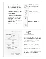
Replace in reverse order.
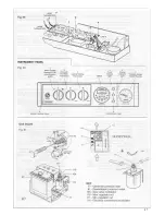
TO REMOVE/REPLACE THE MAIN
SWITCH (Fig. 82).
7.22.7
7.23
Remove the front panel from the outer
casing (sect. 7.3) and lower the instrument
panel (sect.-7.16.2 & 3), and remove the
control box cover (7.31.2/3).
7.23.1
7.23.2
Pull off the switch knob. Remove the switch
out from the instrument panel by pressing
the clamp springs (Fig. 82).
Detach the wires that connect to the switch
- make sure that these wires are later
reconnected to the same poles (Fig. 94).
7.23.3
7.23.4
Replace in reverse order.
TO REMOVE/REPLACE THE WATER
PRESSURE GAUGE (Fig. 83).
7.23.5
Remove the front panel from the outer
casing (sect. 7.3) and lower the instrument
panel (sect. 7.16.2 & 3).
Remove the lower grating (sect. 5.4.2).
7.23.6
7.24
Close the heating system on/off valves and
drain the water from the drain point on the
heating system (Fig. 93).
7.24.1
Unscrew the fitting that secures the
pressure gauge probe.
7.24.2
Remove the gauge from the instrument
panel by pressing its fastening springs.
Replace in reverse order.
7.24.3
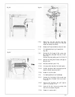
TO REMOVE/REPLACE THE OVERHEAT
THERMOSTAT
Remove the front panel from the outer
casing (sect. 7.3) and lower the instrument
panel (sect. 7.16.2 & 3), and remove the
control box cover (7.31.2/3).
7.24.4
7.24.5
7.24.6
Remove lower grill and right side of the
casing (sect. 5.4.2 & 5).
Unscrew the plastic cover and locknut that
fastens the overheat thermostat and remove it.
7.25
Remove the three wires that connect to the
overheat thermostat - making sure that
these
wires
will
subsequently be
reconnected to the same poles (Fig. 94).
7.25.1
Remove the split pin and pull the
thermostat sensor from its pocket
7.25.2
Replace in reverse order.
TO REMOVE/REPLACE THE ELECTRIC
CONTROL BOARD (PCB)
Remove the front panel from the outer
casing (sect. 7.3) and lower the instrument
panel (sect. 1.16.2 & 3).
Unscrew the 2 screws holding the control
box cover and remove.
Disconnect mains cables and any other
connections (room thermostat and frost
thermostat if fitted).
Detach the connectors from the board.
Detach the PCB board from its base by
unscrewing the six screws.
Replace in reverse order (ensure ‘all
electrical connections are made correctly).
Having replaced PCB recommission boiler
on heating mode (sect. 6.15).
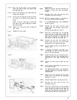
TO REMOVE/REPLACE THE DIFFEREN-
TIAL PRESSURE SWITCH (Fig. 87).
Remove the front panel from the outer
casing and the combustion chamber front
cover (sect. 7.3 & 4).
Detach the wires that connect to the
pressure switch, make sure that these wires
are later reconnected to the same poles
(Fig. 94).
Unscrew the two screws that fasten the
pressure switch to the back of combustion
chamber.
Remove the two silicone tubes.
Ensure tubes are connected correctly (Fig.
87) avoiding kinks.
Replace in reverse order ensuring that the
- t a p p i n g i s c o n n e c t e d t o t h e t u b e
terminating inside the case and the +
tapping
is
connected
to the tube
terminating at flue ring (Fig. 87 and 94).
TO REMOVE/REPLACE THE PUMP
(Fig. 88)
Remove the front panel from the outer
casing (sect. 7.3) and lower the instrument
panel (sect. 7.16.2 & 3).
Remove lower grill right side of the casing
(sect. 5.4.2 & 5) lower the electric box
(sect. 7.16.2 & 3).
38
Summary of Contents for CSI 85
Page 26: ...27...
Page 42: ......
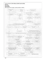
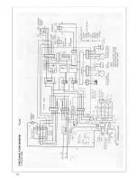
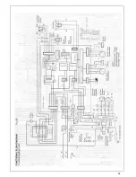
Page 45: ...SECTION 9 ELECTRICAL SYSTEM DIAGRAM Fig 94 46...
Page 46: ...47...
Page 47: ......
Page 48: ...49...
Page 52: ......
Page 55: ...Chartists Way Morley Leeds LS27 9ET Telephone 0113 252 7007 Tfax 0113 238 0229...


