


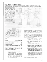


Cut a 105 mm diameter hole through the ceiling
and/or roof, at the point previously marked.
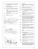
Fit a roof flashing sleeve (7 Fig. 43) to the roof,
available from Ravenheat Manufacturing.
Insert the-Vertical Flue terminal assembly through
the flashing plate from the outside.
Fix the appliance to the wall, locating onto the top
coach bolts. Fit the two lower coach bolts and tighten
all four securing bolts.
Measure the vertical distance between the top of the
flue (Fig. 42) and the bottom of the flue terminal
assembly (Fig. 41). The measurements should be
taken from the outer diameter of the flue.
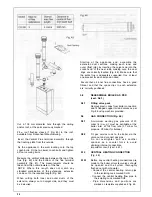
NOTE: Where this length does not match any
standard combination of the extensions, extension
can be cut to the required length (Fig. 44).
When cutting both inner and outer ducts of the
extension, always cut on spigot side, and they must
be de-burred.
Starting at the appliance end, assemble the
extension duct sections, making each inner and
outer (flue) joint by inserting the spigot end into the
socket end of the next tube, making sure the seal
rings are correctly located (Fig. 44). Make sure that
the entire flue is adequately supported. Use at least
one bracket for each extension used.
Ensure that all inner flue connections have a good.
fit/seal, and that the space clips in each extension
are correctly positioned
5.8
5.8.1
5.9
5.9.1
5.9.2
5.10
5.10.1
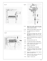
REASSEMBLE BOILER AS PER
(sect. 5.6.1)
Fitting valve pack
Remove plastic caps from boiler connection
and fit flanged copper tail and valves as per
Fig. 46 using washers provided.
GAS CONNECTION (Fig. 46)
A minimum working gas pressure of 20
mbar (8 in w.g.) must be available at the
boiler inlet at full flow rate (37 mbar for
propane, 29 mbar for butane).
Fit gas service cock to the boiler via the
union nut and connect gas pipe.
Do not overtighten and use another
spanner as a counter force to avoid
straining internal connections.
Important consult (sect 4.5.1).
CENTRAL HEATING CONNECTION
(Fig. 46)
Before any central heating connections are
made to the boiler all system valves should
be opened and the system thoroughly
flushed out with cold water.
- Connect the central heating return pipe
to the isolating cock marked CHR.
- Connect the central heating flow pipe to
the isolating cock marked CHF.
- Pipe dimensions and positions are
marked on template supplied and fig. 45.
24
Summary of Contents for CSI 85
Page 26: ...27...
Page 42: ......
Page 45: ...SECTION 9 ELECTRICAL SYSTEM DIAGRAM Fig 94 46...
Page 46: ...47...
Page 47: ......
Page 48: ...49...
Page 52: ......
Page 55: ...Chartists Way Morley Leeds LS27 9ET Telephone 0113 252 7007 Tfax 0113 238 0229...