4
Status Symbols
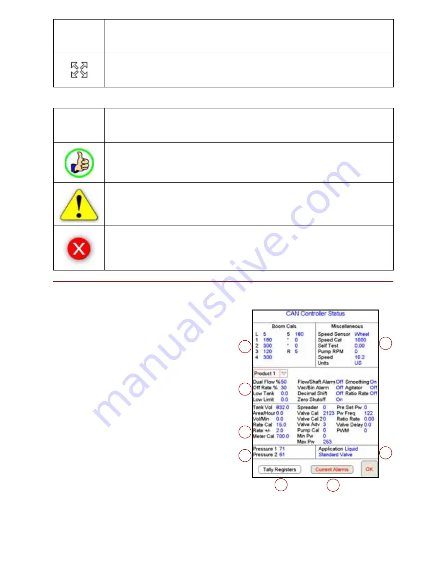
CAN Controller Status Screen
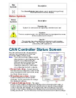
See the screen and the corresponding
sections for a description of the CAN
Controller Status screen areas.
Note:
The CAN Controller Status screen
shown above is only displayed if the
Viper Pro is configured as the
CANbus control console. Review
the
Viper Pro Installation and
Operation Manual
for information
on configuring the field computer.
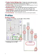
1.
Boom Cals Area
- Current booms
that have been configured. Touch in this
area to assign booms to products using
the Boom Select screen.
2.
Miscellaneous Area
- Various
system settings and actual system
readouts. Touch in this area to change
the displayed settings.
3.
Feature Settings Area
- The upper
portion of the Feature Settings area displays the selected product node or
control channel. Use the drop down selection box to select other available
control channels and display the programmed channel settings.The lower
portion of the Feature Settings area displays the current alarm and feature
setting selections. Touch in this area to access the feature and alarm settings.
The
Zoom Extents icon
allows you to quickly bring all map
information back onto the display.
Status
Symbols
Description
Thumbs Up:
System is normal and all operating conditions are met.
Caution:
There is a system alert. It is recommended to investigate the cause
of the condition and correct it.
Red ‘X’:
The system has encountered a critical error and requires
immediate attention. The condition must be corrected before
proceeding with application.
Map
Symbols
Description
1
2
3
5
4
8
7
6
Summary of Contents for Viper Pro
Page 1: ...Software Version 3 10 Viper Pro Quick Reference Guide...
Page 23: ...22...

