Raven viper 4+ Service Manual Download Page 7

                                Viper 4+ Service manual I V1.0  


Viper 4+ service manual-EN-V1.0 I

 Pag 7/

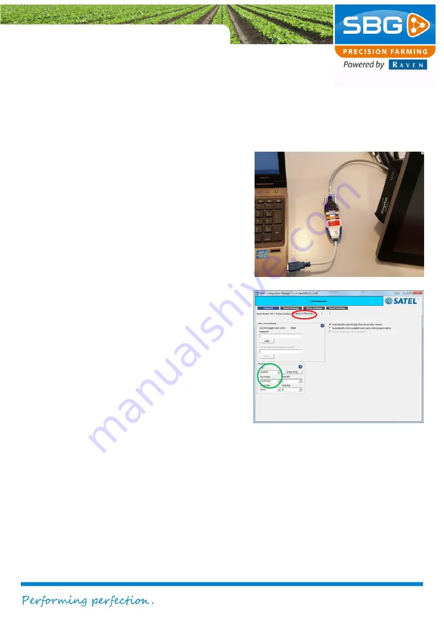
3. Connect to internal Satel 

radio modem 

Take the following steps to connect with a serial 
connection to the internal Satel radio modem: 

1.  Connect a serial cable or USB-to-Serial 

converter from your desktop PC/laptop to 
the SUB-

D9 connector with label “RTK-

COR

” (Figure 12). In both the Harness, 

In-Cab VPR4 ISO (11158000064) and 
the Harness, In-cab (terminal) VPR4 
(SBG13711-09) the 

RTK-COR 

connector 

is located just behind the Viper 4+ field 
computer.  

2.  Start the 

Satel Configuration Manager

. If 

this tool is not available on your 
computer, download the tool from the 
SBG website.  

3.  Go to 

Program Preferences 

(see red 

circle in Figure 13).  

4.  Choose in the 

serial port

 section the 

correct 

port 

and 

baudrate 19200 

(see 

green circle in Figure 13). If you do not 
know which COM-port of your computer 
is used, look in the Windows Device 
Manager. In point 4 of chapter 2 is 
explained how to do this. 

5.  If the correct port is entered, press 

Connect

. The blue status bar at the top 

of the screen will indicate 

Connected


after the connection is established. Now 
all the functionality of the Satel 
Configuration Manager are available 
(check diagnostics, check firmware 
version, set multiple settings and update 
firmware). If the connection is not 
established try a null modem (00-289-
2430374) in the serial cable.   


Figure 12 Connection to internal Satel radio modem


Figure 13 Satel Configuration Manager Preferences


Summary of Contents for viper 4+

Page 1: ...CONFIGURATION MANUAL Viper 4 service manual ...

Page 2: ... I V1 0 Viper 4 service manual EN V1 0 I Pag 2 9 Content 1 Remote Support 3 2 Connect to internal Septentrio GPS receiver 5 3 Connect to internal Satel radio modem 7 4 Capture screenshots on a Viper 4 8 5 COM Port overview 9 ...

Page 3: ...s in the displayed screen of the SBGuidance Loader Request Support Figure 3 or on the button with the red circle in SBGuidance Figure 2 A session ID appears The customer should give the session ID to the technical service specialist 3 Go to the SlingShot Portal https portal ravenslingshot com 4 Login to the SlingShot Portal 5 Go to Manage Remote support 6 Fill in the received session ID from the c...

Page 4: ...I V1 0 Viper 4 service manual EN V1 0 I Pag 4 9 7 A screen like Figure 5 appears The technical service specialist is able to take over all the functionality of the screen similar to TeamViewer Figure 5 Remote Support session ...

Page 5: ...tor is located nearby the first DT connector in the cable In the Harness In cab terminal VPR4 SBG13711 09 the nmea connector is located just behind the Viper 4 field computer When you use a Harness SBG VPR4 Adapter M12 SBG13711 11 use the NMEA output connector with a NMEA cable SBG10880 to connect 2 Open Septentrio RxControl on your computer If Septentrio RxControl is not available on your compute...

Page 6: ...converter search for a USB serial Port Figure 9 5 If the correct COM Port is not in the list behind serial connection choose in the COM Port selection box new connection Figure 10 6 Press Next 7 Select the correct serial port behind Serial Port Figure 11 and give the connection a name behind Connection Name Always use for the name COMX_auto X is in this case the port number 8 Press Finish The conn...

Page 7: ...the SBG website 3 Go to Program Preferences see red circle in Figure 13 4 Choose in the serial port section the correct port and baudrate 19200 see green circle in Figure 13 If you do not know which COM port of your computer is used look in the Windows Device Manager In point 4 of chapter 2 is explained how to do this 5 If the correct port is entered press Connect The blue status bar at the top of...

Page 8: ... Figure 14 If this is successful you get a message that a screenshot has been saved Figure 15 3 Go to Info System Debug 4 Press on the export button see red circle in Figure 16 The screenshots will be exported together with all the other diagnostics data logs error log and trace log to a diagnostics folder on your USB drive This can take a couple of minutes Make sure that you only remove the USB d...

Page 9: ...GPS receiver setup wizard in the SBGuidance Configurator Figure 17Figure 17 See Table 1 for an overview of the COM ports on a Viper 4 Port name Viper 4 Port name Viper 4 Description dev ttymxc0 COM4 VRA NMEA2 on Viper 4 terminal harness dev ttymxc2 COM1 AsteRx4 GPS receiver dev ttyUSB1 COM5 Radio COM5 on Viper 4 terminal harness dev ttyUSB2 COM3 COM3 on Viper 4 terminal harness Table 1 Port overvi...

Reviews: