background image

016-0171-694 Rev. B

31

SPREADER OPERATION

DIAGNOSTICS

Select Diagnostics to access system information, tests, and diagnostic trouble codes (DTCs).

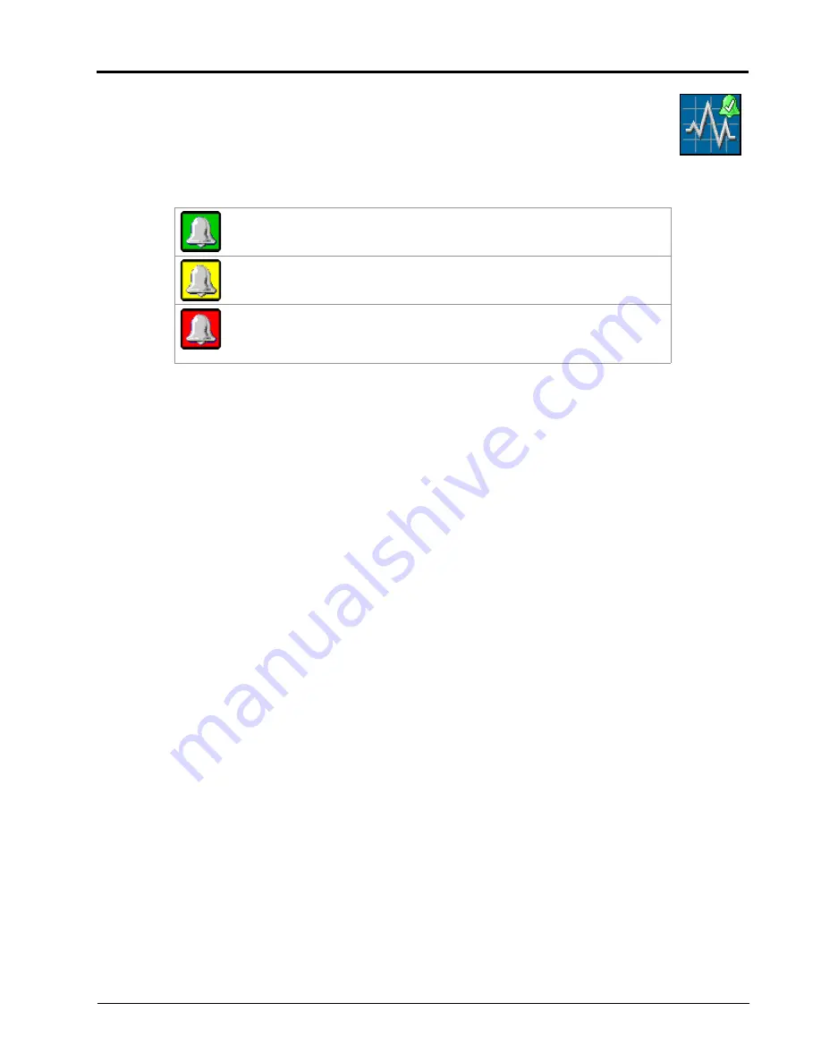
The DTC Status indicator is displayed on the Diagnostics softkey and provides a visual indicator of 

the system status during field applications. The status indicator provides the following display 

states:

OK. 

The system status is normal and no alarm conditions are currently 

present.

Caution. 

A minor alarm condition has been detected. The control system is 

operating normally, however, the system has detected that a condition exists 

which could impact the current application.

Critical. 

A critical system condition has been encountered. The control 

system is not responding as expected and the operator should cease 

application and troubleshoot the issue before resuming operations. The 

system will not apply in this state

Diagnostics

Summary of Contents for RCM

Page 1: ...Copyright 2019 2020 2021 Raven Rate Control Module RCM Operation Manual for Dry Manure Litter Applications 016 0171 694 Rev C 1 2021 E36584 ...

Page 2: ...aven Industries shall not be held responsible for any modifications or repairs made outside our facilities nor damages resulting from inadequate maintenance of this system As with all wireless and satellite signals several factors may affect the availability and accuracy of wireless and satellite navigation and correction services e g GPS GNSS SBAS etc Therefore Raven Industries cannot guarantee t...

Page 3: ...serve the following safety measures when operating the implement after installing this Raven system Do not operate this Raven system or any agricultural equipment while under the influence of alcohol or an illegal substance Be alert and aware of surroundings and remain in the operator seat at all times when operating this Raven system Do not operate the implement on any public road with this Raven...

Page 4: ...ural chemicals or products After handling or applying agricultural chemicals Thoroughly wash hands and face after using agricultural chemicals and before eating drinking or using the restroom Thoroughly flush or rinse equipment used to mix transfer or apply chemicals with water after use or before servicing any component of the application system HYDRAULIC SAFETY When installing or servicing a hyd...

Page 5: ... as much as possible Proper hose routing should Secure hoses and prevent hoses from hanging below the implement Provide sufficient clearance from moving components and operational zones around shafts universal joints and suspension components pulleys gears belts and chains moving linkages cylinders articulation joints etc Protect hoses from field debris and surrounding hazards e g tree limbs fence...

Page 6: ...ot points Clamp harnessing securely to force controlled movement of the harness Avoid abrasive surfaces and sharp edges such as sheared or flame cut corners fastener threads or cap screw heads hose clamp ends etc Do not connect affix or allow harnessing to come into contact with components with high vibration forces hot surfaces or components carrying hot fluids beyond the temperature rating of ha...

Page 7: ...ration section on page 21 for additional assistance with the dynamic calibration feature CLEANOUT MODE The clean out mode is used to compensate for the end of a load when the beaters or spinners are no longer full The apron chain will continue to speed up until it is at full speed The controller will resume normal operation when the spreader has been refilled to a level above the trigger weight Re...

Page 8: ...pelled dry manure and litter applicators Initial Setup and Navigation Calibration NOTE Prior to using the Raven Rate Control Module control features with any UT display the Raven Rate Control Module electronic control unit ECU must be calibrated for the control system Refer to Chapter 3 Calibration for assistance with completing the calibration wizard This manual assumes that the required control ...

Page 9: ...d with a scale system the Raven Rate Control Module RCM is capable of compensating for varying product density within a spreader load This capability offers optimal consistency of application even when the product composition is highly variable TABLE 1 RCM Machine Types Machine Type Feature Unlock Level Application Type Application Mode Uses Scale Only 0 N A General purpose scale without product c...

Page 10: ...ion Reason 077 0180 198 Auth Code Raven Control Module Lvl 0 to Lvl 1 077 0180 200 Auth Code Raven Control Module Lvl 1 to Lvl 2 077 0180 241 Auth Code Raven Control Module Lvl 2 to Lvl 3 Required for dynamic calibration cleanout mode and gate height monitoring features At Raven Industries we strive to make your experience with our products as rewarding as possible One way to improve this experien...

Page 11: ...spreader box is installed on a truck chassis select the Self Propelled Spreader option for the machine type 3 Enter the application width of the spreader 4 Select the Next button in the lower right corner of the page to proceed FIGURE 1 Name Profile Page 5 The ECU number will remain at 1 6 The Number of Products will also be set to 1 7 Select the Next button in the lower right of the page to proce...

Page 12: ...ntrol for Pull Behind applications NOTE Enable Fan Spinner Control may be used on pull type or truck mounted boxes which are configured with hydraulically driven spreaders or beaters 9 Select the Next button in the lower right corner of the page to proceed FIGURE 3 Setup Fan Spinner RPM 10 Use the drop down list to select the Granular Fertilizer option 11 Select the Next button in the lower right ...

Page 13: ...ion 13 Select the Next button in the lower right corner of the page to proceed FIGURE 5 Setup Application Type Product 1 14 No Auxiliary Drivers are currently used on the Dry Manure Litter configurations 15 Ensure all Drivers Auxiliary Driver 1 6 are set to None 16 Select the Next button in the lower right corner of the page to proceed ...

Page 14: ... this page 18 Select the Next button in the lower right corner of the page to proceed FIGURE 7 Section Summary 19 Use the drop down list to select Product Scale 20 Assign the Product Scale 1 to Product 1 by placing a check mark in the box next to Product Scale 1 21 Select the Next button in the lower right corner of the page to proceed ...

Page 15: ...It is highly recommended to verify the scale calibration with a known weight of at least 25 of the total scale capacity after initial scale calibration to ensure scale accuracy 23 Enter the number of pickups which the sensor reads per revolution of the shaft as the RPM 1 Calibration Number NOTE If the number of pickups is changed this value must be changed accordingly 24 Enter an initial value for...

Page 16: ...udible alarm if the PTO shaft speed nears the limit value 26 Select the Next button in the lower right corner of the page to proceed FIGURE 10 Setup Fan Spinner RPM Calibration 27 Place a check mark in the box next to Product 1 NOTE This will assign the RPM sensor to Product 1 and disable product application unless the RPM sensor detects PTO shaft rotation This is a safety catch to prevent belt mo...

Page 17: ...0 Hz Refer to Chapter 6 Machine Settings for machine specific settings 35 PWM High Limit is set to 100 36 PWM Low Limit is set to 20 37 PWM Startup is set to 25 NOTE The High Low and Startup PWM values can be adjusted per each machine configuration as desired by the operator 38 Select the Next button in the lower right corner of the page to proceed FIGURE 13 Setup PWM RATE SENSOR WITHOUT GATE HEIG...

Page 18: ...ight value NOTE Refer to Reference Chapter 6 Machine Settings for assistance with initial and default values on specific make and model equipment During initial setup it is recommended to enter the maximum gate height value Spreader constant values shown in Chapter 6 Machine Settings are based upon max gate height opening During normal operation of the system manually adjust the gate height value ...

Page 19: ... for assistance with initial and default values on specific make and model equipment During initial setup it is recommended to enter the maximum gate height value Spreader constant values shown in Reference Chapter 6 Machine Settings are based upon max gate height opening During normal operation of the system the system will monitor the gate height and automatically adjust the spreader constant c ...

Page 20: ...election drop down menu from Predefined or RX to Rate Bump or RX 46 Select the desired Rate Selection NOTE For predefined rate entries use Predefined or RX selection For rate bump abilities use Rate Bump or RX selection 47 Ensure the Display Smoothing box is checked 48 Decimal Shift should remain at 0 49 Select the Next button in the lower right corner of the page to proceed FIGURE 17 Setup Rates ...

Page 21: ... of the page to proceed FIGURE 18 Setup Alarms 54 Review the Setup Summary 55 Select the Next button in the lower right corner of the page to complete the profile setup NOTE Select the Back button in the lower left corner of the page to return to the previous page if needed FIGURE 19 Setup Summary ...

Page 22: ...CHAPTER 3 20 RCM Dry Manure Litter Setup Guide ...

Page 23: ...navigate to the Rate Sensor Setup Page 1 From the RCM home page select the Tools button along the right side of the page 2 Select the System Settings tab and then the Rate Sensor Setup button FIGURE 1 Setup Rate Sensor Page 3 Select the Dynamic Cal Setup button RCM Menu Tools Menu System Settings UT Menu Rate Sensor Setup ...

Page 24: ... value can be decreased however rate fluctuation may be observed If excessive rate fluctuation is occurring increase the value ADJUSTMENT SENSITIVITY The Adjustment Sensitivity percentage is used to set how aggressively the controller will adjust the Density Factor It is recommended to leave this setting at the default setting of 50 unless otherwise instructed If the total applied weight displayed...

Page 25: ...trigger weight Configuration of the cleanout mode consists of two settings Trigger Weight and Cleanout Duration To enable the cleanout mode 1 From the RCM home page select the Tools button along the right side of the page 2 Select the System Settings tab and then the Rate Sensor Setup button 3 On the Setup Rate Sensor page press the Cleanout Setup button to access the Cleanout settings FIGURE 3 Se...

Page 26: ...wer duration value should be used If the angle of the material left in the spreader is more gradual a higher duration value should be used The default value is 15 and may be adjusted by the operator based upon the behavior of the material being applied GATE HEIGHT SENSOR CALIBRATION To access settings for Gate Height Calibration navigate to the Rate Sensor Setup Page 1 From the RCM home page selec...

Page 27: ... on page 25 If the specific mV Per Length value is not known refer to the Procedural Calibration section on page 26 MANUAL CALIBRATION If the specific mV Per Length value is known mV in select the Manual Calibration button and enter the known value into the field under the Manual Calibration tab to calibrate the gate height sensor FIGURE 7 Manual Gate Height Calibration ...

Page 28: ...e check mark in the lower right corner of the page to complete the procedural calibration ADJUST THE MANUFACTURER SCALE CALIBRATION VALUE The manufacturer scale calibration number is a good starting point to achieve a basic scale calibration However it is recommended to verify the scale calibration with a known weight for optimal performance NOTE Refer to Table 2 Scale Settings on page 43 for manu...

Page 29: ...page FIGURE 10 Scale Setup Page 4 Load a known weight of product into the implement tank or bin NOTE It is recommended to use a known weight of at least 25 of the total scale capacity to obtain a more precise scale calibration slope 5 Enter the current scale weight reading into the Previous Prev field on the Scale Calibration page ...

Page 30: ...n the tank or bin into the Actual field on the Scale Calibration page 7 Select the Calibrate button FIGURE 12 Scale Weight Entry on the Scale Calibration Page 8 Review the confirmation prompt and select the Accept button in the lower right corner of the page The scale calibration has been adjusted for the known weight of product in the tank or bin ...

Page 31: ...rge feature Quick Start may also be used to prime the spreader However Quick Start runs for a set duration of 15 seconds and can be canceled by toggling the master switch off Using Quick Start will allow the system to add to applied product tallies With the beater running toggle the master switch ON and press the Quick Start button in the lower right corner of the RCM run page The Quick Start feat...

Page 32: ...ional information about the RCM softkeys HOME Touch the Home softkey to quickly return to the Home page and access the primary RCM operation information Use these pages to monitor the system during field operations TOOLS Select the Tools Menu softkey to access the calibration prompts See Chapter 4 System Setup for additional assistance with system calibration features and settings TOTALS Select To...

Page 33: ...play states OK The system status is normal and no alarm conditions are currently present Caution A minor alarm condition has been detected The control system is operating normally however the system has detected that a condition exists which could impact the current application Critical A critical system condition has been encountered The control system is not responding as expected and the operat...

Page 34: ...duct may be customized to the operators preferences 2 Actual Rate Actual application rate 3 Target Rate Target application rate 4 Manual Automatic Mode Toggle manual or automatic rate control modes 5 Product On Off Switch Toggle a product on or off 6 Preset Rate Buttons Provides the user with preset rates to quickly change the application rate during field applications 7 Tank Bin Charge Touch and ...

Page 35: ...t speed feature Applied Area The field area covered during the current field application Total Volume Applied The total product volume applied for the specific product displayed RPM 1 The RPM of the PTO shaft Gate Height The current gate height setting Product Density The current density factor of the product Dry Rate Current application rate in pounds kilograms per minute as read by an encoder 8 ...

Page 36: ...ation For more information on the Precision Farming Setup button refer to the Raven Rate Control Module Operation Manual P N 016 0171 637 SYSTEM SETTINGS The system settings provides access to settings and options which allow the operator to adjust the system configuration values as needed to maintain proper control of the system The table below describes each button in detail Applicator Setup Sys...

Page 37: ...des options to access a Current Totals Device totals and Distance totals tabs Button Description Control Valve Setup The Control Valve button allows the user to adjust the following settings for each product Valve Response Rate Control Dead Band Valve Delay Enable PWM Smart Control Rate Sensor Setup Allows the operator to modify edit the calibration value for the encoder used on the control channe...

Page 38: ... down list These list of tests will vary by product configuration DIAGNOSTIC TROUBLE CODES This tab lists Active and Inactive diagnostic trouble codes as well as the ability to Clear the active codes SYSTEM SUMMARY Displays information configured during the setup process but does not provide the option to modify the configuration PRODUCT SUMMARY The Product Summary provides a brief summary for all...

Page 39: ...PTER5STAND ALONE SCALE OPERATION STAND ALONE SCALE INITIAL CALIBRATION 1 Select Scale as the Machine Type FIGURE 1 Name Profile 2 Enter a Profile Name 3 Press Next 4 Select the check box es next to the desired Scale s you want to monitor ...

Page 40: ... Total Scale option may be used to monitor the combined weight of all the selected scales 5 Press Next 6 Enter the Scale Total Calibration Number Refer to Chapter 6 Machine Settings for machine specific scale information FIGURE 3 Scale Setup 7 Press Next 8 Review the scale configuration on the Setup Summary page ...

Page 41: ...nfiguration If the configuration is correct press Next SCALE RUN PAGE OVERVIEW The image below is an example of a typical run page FIGURE 5 RCM Main Page SCALE PAGE The scale page displays graphic and numeric representations of the scales as well as options to zero a scale or view the current gross scale weight Scale Page Main Setup Totals Diagnostics ...

Page 42: ...n Function Operation 1 Scale Selection If multiple scales are detected select the scale information to display on the main page 2 Weight Displays the current weight on the selected scale 3 Tare Select the Tare button to zero out the selected scale If the combined weight scale is selected this will display as Zero 4 Scale Graphics Show a graphical representation of the weight on each scale 5 Gross ...

Page 43: ...guration SYSTEM SETTINGS The Systems Settings Tab allows the user to modify the current scale calibration FEATURE UNLOCKS To activate additional features available for the RCM enter the Activation Key to access these features NOTE Contact a local Raven dealer for additional information regarding available features for your specific application and for assistance with purchasing activation keys TOT...

Page 44: ... down list These list of tests will vary by product configuration DIAGNOSTIC TROUBLE CODES This tab lists Active and Inactive diagnostic trouble codes as well as the ability to Clear the active codes SYSTEM SUMMARY Displays information configured during the setup process but does not provide the option to modify the configuration PRODUCT SUMMARY The Product Summary provides a brief summary for all...

Page 45: ... Way Kuhn SB SBX CB Truck Mounted X700 X900 PXL1100 Fan Spinner RPM 1 1 1 RPM 1 Cal 1 1 1 RPM Low Limit 400 800 800 RPM High Limit 2000 1200 1500 Coil Frequency Hz 100 100 100 PWM High Limit 100 100 100 PWM Low Limit 20 20 20 PWM Start Up 25 25 25 Pulses Revolution 200 942 2180 Spreader Constant 6 5 1 4 4 Box Dependent 29 6 26 3 34 8 Gate Height Max 48 in 121 9 cm 51 in 129 5 cm 53 in 134 6 cm 70 ...

Page 46: ...CHAPTER 6 44 RCM Dry Manure Litter Setup Guide ...

Page 47: ...er s responsibility The Return Materials Authorization RMA number must appear on the box and all documentation including proof of purchase must be included inside the box to be sent to Raven Industries WHAT WILL RAVEN INDUSTRIES DO Upon confirmation of the warranty claim Raven Industries will at our discretion repair or replace the defective product and pay for the standard return freight regardle...

Page 48: ... claim and send it to Raven Industries for final approval The freight cost to Raven Industries will be the customer s responsibility The Return Materials Authorization RMA number must appear on the box and all documentation including proof of purchase must be included inside the box to be sent to Raven Industries In addition the words Extended Warranty must appear on the box and all documentation ...

Reviews: