


4
Manual No. 016-0230-018
27
PowerGlide Plus
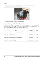
FIGURE 3.
Port Plugs Removed from the AutoBoom Valve
3.
Use an Allen wrench to remove the plugs from Ports 3A and 3B.
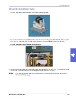
FIGURE 4.
Orifice Fitting Removed from the AutoBoom Valve
4.
Remove the orifice fittings from Ports 3A and 3B.
Important:
Tip the AutoBoom valve on its side and use the Allen wrench to remove the orifice from the cavity,
taking care not to let the fitting fall into the valve.
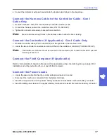
FIGURE 5.
Port Plug Reinstalled on the AutoBoom Valve
Orifice Fitting
Removed - Keep for
Future Use
Summary of Contents for AutoBoom RoGator 54 Series
Page 1: ...AutoBoom Installation Manual RoGator 54 Series 1996 Older ...
Page 9: ...2 Manual No 016 0230 018 5 Introduction JIC fitting M ORFS fitting SAE O ring fitting ...
Page 10: ...Chapter 2 6 RoGator x54 Series 1996 Older AutoBoom Installation Manual ...
Page 20: ...Chapter 3 16 RoGator x54 Series 1996 Older AutoBoom Installation Manual Hydraulic Schematic ...
Page 37: ...4 Manual No 016 0230 018 33 PowerGlide Plus PowerGlide Plus Hydraulic Schematic ...
Page 43: ...4 Manual No 016 0230 018 39 PowerGlide Plus Gen II Cabling ...
Page 44: ...Chapter 4 40 RoGator x54 Series 1996 Older AutoBoom Installation Manual ...
Page 45: ...4 Manual No 016 0230 018 41 PowerGlide Plus ...
Page 46: ...Chapter 4 42 RoGator x54 Series 1996 Older AutoBoom Installation Manual ...
Page 65: ...5 Manual No 016 0230 018 61 UltraGlide UltraGlide Wiring Schematic Gen I Cabling ...
Page 66: ...Chapter 5 62 RoGator x54 Series 1996 Older AutoBoom Installation Manual Gen II Cabling ...
Page 69: ...6 Manual No 016 0230 018 65 Replacement Parts Sensors ...
Page 70: ...Chapter 6 66 RoGator x54 Series 1996 Older AutoBoom Installation Manual ...