background image

CHAPTER 3

26

AccuFlow™ Vortex and AccuFlow™ HP+ Installation and Operation Manual

15. Install the tee, bleed valve, and check valve into the relief valve adapter. 
16. Install the on/off valve onto the 1” close nipple. 
17. Install pipe adapter into the other end of the on/off valve. 
18. Thread the 1” x 3” long pipe nipple into a pipe adapter. 
19. Thread the other end of the pipe nipple into a 1-1/4” tee. 
20.Install 1-1/4” x 1/2” reducer into the other end of the 1-1/4” tee. 
21. Install an elbow into the 1-1/4 x 1/2” reducer. 
22.Install the hose barb fitting into elbow. 

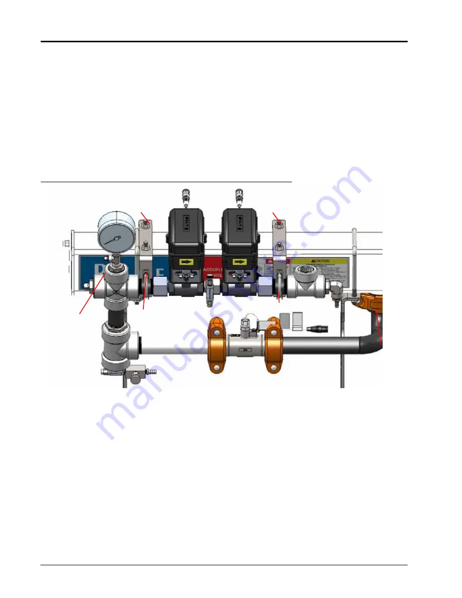
ATTACHING THE GAUGE TREE TO THE COOLER

FIGURE 12. Attaching the Gauge Tree to the Cooler

1. Place the cooler mounting bracket on top of the cooler. 
2. Use the provided large u-bolts to secure the mounting bracket to the cooler. 
3. Place the clamping u-bolts over the horizontal pipe nipples on the assembly. 
4. Feed the ends of the clamping u-bolts into the side of the mounting brackets. 
5. Install the nuts on the end of the clamping u-bolts. 
6. Slide the coupling gasket over the end of the gauge tree that attaches to the flowmeter.
7. Connect the end of the gauge tree to the end of the flowmeter.
8. Use the provided coupling clamp, 1/2” bolts, and 1/2” nuts to secure the gauge tree to the outlet manifold.
9. Tighten the 1/2” nuts to 80 to 100 ft-lbs.

Clamping U-Bolts

Cooler 

Mounting 

Bracket

Gauge Tree

Cooler

Cooler 

Mounting 

Bracket

Clamping U-Bolts

Summary of Contents for AccuFlow HP+

Page 1: ...Copyright 2014 2015 2016 2017 2020 AccuFlow Vortex and AccuFlow HP Installation and Operation Manual 016 0171 573 Rev G 1 2020 E34241 ...

Page 2: ...aven Industries shall not be held responsible for any modifications or repairs made outside our facilities nor damages resulting from inadequate maintenance of this system As with all wireless and satellite signals several factors may affect the availability and accuracy of wireless and satellite navigation and correction services e g GPS GNSS SBAS etc Therefore Raven Industries cannot guarantee t...

Page 3: ...Cooler 22 Check Valve Assembly For Multiple Section Valves Only 23 Refrigerant Line Assembly 24 One Inch Gauge Tree and Valve Assembly 25 Gauge Tree and Valve Assembly 25 Attaching the Gauge Tree to the Cooler 26 Check Valve Assembly For Multiple Section Valves Only 27 Refrigerant Line Assembly 27 Manifold Assembly 28 Dual Inlet Manifold Assembly 28 Dual Inlet Manifold Support Bracket Installation...

Page 4: ... Pressure Cal 51 Default Calibration Values NH3 Pre sets 52 Programming HP Rate Control Viper Pro 53 Adjusting the Rate Cal 56 Operating HP System in HP NH3 Boost Mode 58 Verifying AccuFlow HP Operation 58 Chapter 6 Service and Maintenance 61 Discharging the AccuFlow System 61 Servicing and Storing the AccuFlow System 65 Maintaining the Vortex Cooler 65 Strainer Maintenance Procedure 67 Flow Meter...

Page 5: ...under the influence of alcohol or an illegal substance Be alert and aware of surroundings and remain in the operator seat at all times when operating this Raven system Do not operate the implement on any public road with this Raven system enabled Disable this Raven system before exiting the operator seat Determine and remain a safe working distance from obstacles and bystanders The operator is res...

Page 6: ...d follow instructions provided with the application system to properly discharge NH3 before performing service or maintenance Pressure gauges can fail become plugged or display incorrect pressure Slowly bleed pressure from a previously charged system by opening valves slightly Allow pressure to discharge for an extended period of time Treat every section where NH3 can be trapped as though it is pr...

Page 7: ...ucts and containers Triple rinse and puncture or crush empty containers before properly disposing of them Contact a local environmental agency or recycling center for additional information Always follow safety labels and instructions provided by the chemical manufacturer or supplier Always wear appropriate personal protective equipment as recommended by the chemical and or equipment manufacturer ...

Page 8: ...may damage hydraulic components Stand clear of the implement when starting the system for the first time after installing or servicing hydraulic components in case a hose has not been properly connected or tightened ELECTRICAL SAFETY Always verify that power leads are connected to the correct polarity as marked Reversing the power leads could cause severe damage to the Raven system or other compon...

Page 9: ...or flame cut corners fastener threads or cap screw heads hose clamp ends etc Avoid areas where the operator or service personnel might step or use as a grab bar Do not connect affix or allow hoses to come into contact with components with high vibration forces hot surfaces or components carrying hot fluids beyond the temperature rating of hose components Hoses should be protected or shielded if ro...

Page 10: ...ed to conditions beyond harnessing component specifications Avoid routing harnesses in areas where damage may occur due to build up of material e g dirt mud snow ice etc Avoid routing harnesses in areas where the operator or service personnel might step or use as a grab bar IMPORTANT Avoid applying direct spray or pressure washing of electrical components and connections High pressure streams and ...

Page 11: ...NGER Exposure to anhydrous ammonia can cause severe burning blindness or death Use extreme caution when opening a previously pressurized system To avoid injury or death always wear proper personal protective equipment DANGER DO NOT transport anhydrous ammonia application equipment while it is charged with anhydrous ammonia The AccuFlow Vortex cooler and product lines must be completely discharged ...

Page 12: ... seals will result 4 Resume normal field application until the pressure gauge reads no remaining pressure is left in the AccuFlow system 5 Toggle the control console or vehicle master switch to the off position and verify that all section switches are in the off position 6 Ensure that the tow vehicle is upwind of the NH3 toolbar and application system FIGURE 1 Example Discharge and Shutoff Compone...

Page 13: ...has dispersed check the pressure and temperature gauges to verify that the pressure reads zero and all parts are at an ambient temperature not frosted over 11 Open the secondary bleed valve slowly to relieve any remaining liquid NH3 from the system 12 Recheck and verify that the pressure gauge on the AccuFlow manifold reads zero and that all AccuFlow components are not cold to the touch before ope...

Page 14: ...f an anhydrous ammonia NH3 system Operators must familiarize themselves with the system bleed valve locations and procedures before charging the system with NH3 Primary Bleed Valve Secondary Bleed Valve Vapor Hoses Toolbar Bleed Circuit Pressure Hose Connection Pressure Gauge Temperature Gauge Vortex Cooler Bleed Circuit Vapor Hose Connection Emergency Shut Off Valve Bleed Lines Hose Breakaway Sys...

Page 15: ...r uses a small amount of anhydrous ammonia from the system to reduce the temperature of the ammonia being applied The Raven AccuFlow Vortex system is available in two configurations to match the NH3 application needs AccuFlow Vortex System AccuFlow HP High Performance System ACCUFLOW VORTEX AND ACCUFLOW HP SYSTEMS The AccuFlow Vortex system is available in one or two valve configurations with a si...

Page 16: ... Breakaway Couplers 1 1 2 2 NA Hoses from Nurse Tank Withdrawal Valves to Trailer Bulkhead Couplers 1 1 2 2 Minimized and Equal Length If equipped with bulkhead couplers Hoses from Trailer Bulkhead Couplers to Toolbar Breakaway Couplers 1 1 2 2 Minimized and Equal Length Ensure hose has enough length to turn unit without pinching hose Ensure hose does not drag on ground Do not attach hose to tongu...

Page 17: ...gth Use 3 4 reducers in 1 tee 13 Vapor Tee ID 1 2 NA 14 Vapor Rows 4 NA Attempt to have at least one applicator knife in between each vapor row Toolbar 15 Toolbar or Applicator Unit NA NA Tractor 16 Tractor or Prime Mover NA NA Additional Fittings Additional fittings needed for installation NA NA Schedule 80 steel or equivalent pressure rating Materials rated and approved for NH3 service Additiona...

Page 18: ...CHAPTER 2 14 AccuFlow Vortex and AccuFlow HP Installation and Operation Manual FIGURE 1 Application Unit System Components 1 2 3 4 5 6 7 8 9 10 11 12 13 14 16 15 ...

Page 19: ...nd the overall service we provide We appreciate the opportunity to see ourselves as our customers see us and are eager to gather ideas on how we have been helping or how we can do better To serve you best please send an email with the following information to techwriting ravenind com AccuFlow Vortex and AccuFlow HP Installation and Operation Manual 016 0171 573 Rev G Any comments or feedback inclu...

Page 20: ...CHAPTER 2 16 AccuFlow Vortex and AccuFlow HP Installation and Operation Manual ...

Page 21: ... local Raven dealer for more information and assistance When installing hoses cables and wires always take care that they cannot be pinched cut or otherwise damaged during normal operation FIGURE 1 Typical Vortex System Single and Dual Valve DANGER Anhydrous ammonia can cause severe burning blindness or death Refer to Discharging the AccuFlow System section on page 5 or page 61 and follow the proc...

Page 22: ...the cooler with the base lip facing left 5 Install the 7 16 u bolt from the top of the cooler so the threaded portion of the U bolt is through the two holes on top of the mounting bracket 6 Thread and secure the 7 16 nuts to the threaded ends of the 7 16 u bolt 7 Place the second mounting bracket assembly approximately 7 from the right end of the cooler with the base lip facing left 8 Install the ...

Page 23: ... cooler 2 Slide the bent end outlet manifold into the coupling gasket 3 Place the two parts of the coupling clamp over the coupling gasket so the bolt holes are above and below the outlet manifold 4 Using two 1 2 bolts and two 1 2 nuts to secure the coupling clamp to the cooler and the outlet manifold Tighten the 1 2 nuts to 80 to 100 ft lbs Slide the coupling gasket over the straight end of the o...

Page 24: ...the two parts of the coupling clamp over the coupling gasket so the bolt holes are above and below the outlet manifold FIGURE 6 Clamp Installation Detail 7 Using two 1 2 bolts and two 1 2 nuts to secure the coupling clamp to the flow meter and the outlet manifold 8 Tighten the 1 2 nuts to 80 to 100 ft lbs 1 2 Bolts Outlet Manifold Coupling Gasket 1 2 Nuts Coupling Clamp Flow Meter Flow Direction C...

Page 25: ...n off valve Verify that the 90 hose barb fitting if located at below the pipe 6 Secure the gauge tree manifold to the controller valve 7 Install the needle valve into the needle valve port of the gauge tree manifold 8 Install the straight hose barb fitting into the end of the needle valve 9 Install the transducer into the transducer port of the gauge tree manifold 10 Screw the pressure gauge into ...

Page 26: ...utlet manifold 4 Tighten the 1 2 nuts to 80 to 100 ft lbs 5 Install a clamping u bolt over the top of the gauge tree so the threaded portion of the u bolt is through the two holes on the pipe support bracket 6 Thread and secure the 3 8 nuts to the threaded ends of the clamping u bolt 7 Loosely tighten the 3 8 nuts 8 Repeat steps 5 7 for with the second clamping u bolt 9 Tighten the 3 8 nuts that s...

Page 27: ...bly 1 Apply PTFE thread sealant to all threaded joints 2 Install the pipe nipple into the top of the fitting tee 3 Attach the check valve to the pipe nipple with the flow direction as shown in Figure 9 NOTE Refer to the spare parts list in Chapter 8 System Diagram and Replacement Parts for a list of replacement parts Pipe Nipple Check Valve Fitting Tee Gauge Tree 1 4 Bleed Valve Flow Direction Rel...

Page 28: ...the 90 hose barb fitting 3 Secure the hose clamp over the 90 hose barb fitting 4 Slide a hose clamp over the other end of the refrigerant line 5 Slide the refrigerant line over the straight hose barb fitting 6 Secure the hose clamp over the straight hose barb fitting 7 Secure the refrigerant line to the outlet manifold with a cable tie 90 Hose Barb Fitting Straight Hose Barb Fitting Hose Clamp Hos...

Page 29: ... 4 x 3 pipe nipple into one of the side ports on 1 1 4 cross 10 Install a 1 1 4 x 1 2 reducer into the other side of the 1 1 4 cross 11 Install the pressure gauge assembly into the top of 1 1 4 cross 12 Thread a pipe adapter onto the other end of the 1 1 4 x 3 pipe nipple 13 Install the control valve into the pipe adapter 14 Install a 1 relief valve adapter and 1 close pipe nipple into the other e...

Page 30: ...RE 12 Attaching the Gauge Tree to the Cooler 1 Place the cooler mounting bracket on top of the cooler 2 Use the provided large u bolts to secure the mounting bracket to the cooler 3 Place the clamping u bolts over the horizontal pipe nipples on the assembly 4 Feed the ends of the clamping u bolts into the side of the mounting brackets 5 Install the nuts on the end of the clamping u bolts 6 Slide t...

Page 31: ...ed joints 2 Install the pipe nipple into the top of the fitting tee 3 Attach the check valve to the pipe nipple with the flow direction as shown in Figure 9 NOTE Refer to the spare parts list in Chapter 8 System Diagram and Replacement Parts for a list of replacement parts REFRIGERANT LINE ASSEMBLY FIGURE 14 Refrigerant Line Assembly Check Valve Gauge Tree 1 4 Bleed Valve Flow Direction Relief Val...

Page 32: ...raight hose barb fitting MANIFOLD ASSEMBLY There are variations in inlet manifolds Locate the appropriate inlet manifold below and follow the appropriate instructions to install your inlet manifold DUAL INLET MANIFOLD ASSEMBLY FIGURE 15 Standard Inlet Manifold Assembly FIGURE 16 Reverse Inlet Manifold Assembly 1 Apply PTFE thread sealant to all threaded joints 2 Install the 2 pipe nipple into the ...

Page 33: ... pipe nipple DUAL INLET MANIFOLD SUPPORT BRACKET INSTALLATION FIGURE 17 Standard Inlet Manifold Support Bracket 1 Use three 3 8 bolts and 3 8 nuts to secure the mounting bracket to the inlet manifold support bracket 2 Install two clamping u bolts around the inlet manifold without installing the nuts 3 Place the inlet manifold support bracket against the bottom of the inlet manifold as shown in Fig...

Page 34: ...ng u bolt around the inlet manifold without installing the nuts 3 Place the inlet manifold support bracket against the bottom of the inlet 4 Feed the threaded ends of the u bolts through the holes on the inlet manifold support bracket 5 Install the nuts on the threaded ends of the u bolt on the underside of the inlet manifold support bracket NOTE Depending on location the support bracket may need ...

Page 35: ... to Mounting Plate Primary Bleed Valve Secondary Bleed Valve Vapor Hose Toolbar Hose to Breakaway Bleed Circuit Pressure Hose Connection Pressure Gauge Temperature Gauge Vortex Cooler Bleed Circuit Vapor Hose Connection Emergency Shut Off Valve HP Pump and Hydraulic Valve Steel Vapor Tubes Strainer Magnet Assemblies Check Valve Assemblies Fast Valve Control Valve Pump Inlet Pressure Transducer Ble...

Page 36: ... the connections is flush with the flat side of the node mounting bracket Refer to Figure 21 2 Use three bolts and nuts to secure the control node to the mounting plate 3 Use two bolts and nuts to secure the node mounting plate to the Vortex cooler support bracket Figure 22 FIGURE 22 Installing Control Node Mounting Plate to Vortex Cooler Bracket Node On Mounting Plate Bolt Nut ...

Page 37: ... nipple 2 Install the pipe nipple into the NH3 pump as shown in Figure 23 3 Attach the 2 1 2 coupling to the secure the pump to the outlet on the bottom of the Vortex cooler Refer to Figure 23 4 Use the 1 1 2 coupling to secure the pipe nipple to the flowmeter 5 Torque coupling fasteners to 80 100 ft lbs 6 Use two bolts flat washers and nuts to secure the NH3 pump to the Vortex cooler support brac...

Page 38: ...and Operation Manual INSTALLING HYDRAULIC VALVE FIGURE 24 Installing Hydraulic Valve to Vortex Cooler Bracket 1 Use two bolts nuts and flat washers to attach hydraulic valve to Vortex cooler support bracket as shown in Figure 24 PWM Valve Bolt Nut Flat Washer ...

Page 39: ...ble always turn the pump off in the float position NOTE Route hydraulic hoses so that they are free of twists or kinks and will not be pinched by surrounding mechanisms Ensure at least 3 feet of hose extends past toolbar hitch point Extra hose should be secured to the toolbar away from moving parts or pinch points Take care to prevent dirt or other contaminants from entering hydraulic assemblies w...

Page 40: ...ce between the cooler and the standard so the standard has a full range of motion and does not contact the cooler assembly Also verify that the ball valve hands can be pulled to the full off position with the emergency shut off rope The intake port of the AccuFlow Vortex cooler should be pointing toward the rear of implement and nurse tank NOTE Follow plumbing recommendations on the Component Reco...

Page 41: ...readed joints 2 Install the vapor hose fitting into the vapor port openings WARNING Anhydrous ammonia can cause severe burning blindness or death Always work upwind of an implement with the AccuFlow system If the emergency shut off rope cannot be routed to the vehicle s cab make sure to orient the vehicle to allow the rope to be pulled from a location upwind of the implement Emergency Shut Off Rop...

Page 42: ...to the back of liquid tubes Vapor tubes should be spaced out evenly across the tool bar Avoid connecting vapor tubes on wheel tracks and adjacent rows if possible 4 Route 3 4 tubing from the 3 4 cooler vapor ports to the vapor tube tee as shown in figure Cut tube lengths in equal lengths and allow enough hose to avoid kinking at any folding points Connect one end of the vapor DANGER Anhydrous ammo...

Page 43: ...o reduce risk of uneven application Raven recommends using equal length hose to all vapor knives placed at least 1 row apart BLEED LINE HOSE ROUTING 1 Apply PTFE thread sealant to all threaded joints 2 Route the bleed valve to the front of the tool bar NOTE When routing the bleed line hose avoid pinch points and sharp edges that may damage the hose 3 Secure the bleed hose to the front of the toolb...

Page 44: ...lve 6 Route the 3 8 low pressure hose to a 3 8 hose barb tee on the top side of the cooler FIGURE 32 3 8 Barb Tee 7 Connect to the hose barbs on the top of the cooler This bleeds off into the cooler s vapor chamber and out to vapor tube knives FIGURE 33 Low Pressure Hose Connected to 90 Hose Barb On Cooler To 3 8 Hose Barb on Top Side of Cooler Tee ...

Page 45: ...ints and hoses to identify leaks Fix any leaks and repeat air test before charging the AccuFlow system with anhydrous ammonia If the system is pressurized but the pressure gauge on the system and the gauge on the regulated air source are not equal inspect both gauge for damage and replace if necessary CAUTION To avoid damage to boost pump seals do not run the boost pump dry Be sure to shutdown the...

Page 46: ...CHAPTER 3 42 AccuFlow Vortex and AccuFlow HP Installation and Operation Manual ...

Page 47: ... PROGRAMMING NH3 RATE CONTROL ENTERING BOOM CAL The boom cal for the AccuFlow system can be calculated with the following formula Number of Applicator Knives x Spacing in inches Implement Width EQ 1 FOR EXAMPLE If the implement has 16 knives spaced 30 inches apart the calculated implement width is equal to 480 inches Enter 480 as the boom cal on the control console If a multi section implement has...

Page 48: ...2 Meter Cal Lb N EQ 2 Meter Cal Liter 0 506 Meter Cal Kg N EQ 3 Example 720 Gal 4 22 170 62 Lb N EQ 4 Example 190 Liter 0 506 375 494 Kg N EQ 5 ADJUSTING VALVE CAL Refer to the console Installation and Operation Manual for instructions on entering or adjusting the valve cal NOTE The valve cal may need to be adjusted to speed up or slow down the valve to obtain desired results particularly in appli...

Page 49: ...te of 150 lbs N acre at an average of 5 5 mph and a calculated implement width of 480 inches the required capacity is 150 x 5 5 x 480 66 6 lbs N min 5940 EQ 7 SI Units Given a target application rate of 68 kg N ha at an average of 10 km hr and a calculated implement width of 1220 centimeters the required capacity is 68 x 10 x 1220 13 8 kg N min 60 000 EQ 8 The maximum capacities of the various Acc...

Page 50: ...t This refrigerant then discharges through vapor knives installed behind applicator knives This may add extra NH3 to those rows Options to reduce the amount of refrigerant and row to row variances are 1 Divide the refrigerant by installing additional vapor knives 2 When applying at lower rates use an orifice fitting to control the amount of refrigerant used The table below outlines desired product...

Page 51: ... x Implement Width inches lbN min 5940 EQ 10 To convert lbN Hr lbN lbN min min x 60 EQ 11 INSTALLING AND ORIFICE HOSE BARB FITTING 1 Follow the system bleed down procedure found in the AccuFlow manual before disassembly 2 Remove the EVA hose from the hose barb 3 Remove the current hose barb from the refrigerant inlet port 4 Apply thread sealant to orifice hose barb fitting and re install into refr...

Page 52: ...roduct cable 7 Verify that all motorized valves are in the off position 8 Turn the AccuFlow emergency shut off valve s to the full open position 9 Connect and secure the hose from the AccuFlow implement to the nurse tank 10 Slightly open the nurse tank shut off valve to allow NH3 to slowly pressurize the system NOTE Opening the emergency shut off valve or the nurse tank shut off valves too quickly...

Page 53: ...he console refer to the control console s Operation manual for details 2 Toggle the master switch to the off position 3 Toggle the console to manual control mode 4 Toggle the switch for section 1 boom 1 on If a multi manifold system is in use toggle all sections on Toggle any section switches not in use to their off positions 5 With the master switch in the off position drive at the target applica...

Page 54: ...CHAPTER 4 50 AccuFlow Vortex and AccuFlow HP Installation and Operation Manual ...

Page 55: ...er method for connecting and charging the AccuFlow system 1 Verify that all hoses fittings and mounting bolts are securely fastened or tightened 2 Verify that the AccuFlow flow meter is connected to the flow meter connector on the flow meter cabling 3 Verify that the AccuFlow control valve is connected to the flow or product cable connector 4 Verify the on off valve s are connected to the on off c...

Page 56: ...e system pressures have stabilized verify that pressure gauge readings on the AccuFlow system and the nurse tank are matching If the pressure readings do not match one of the gauges may be defective and should be replaced 15 Enter the pressure gauge reading on the AccuFlow system in the Pressure Cal field on the control console e g Viper Pro or other field computer for both P1 P2 pressure transduc...

Page 57: ...2 To setup the proper HP application mode from CAN Controller Status screen press Application box FIGURE 1 CAN Controller Status Settings and Node 1 Settings 3 In Node 1 Settings screen select HP and press OK 4 The control node will auto select PWM Close Valve and setup the default values as shown below Verify default settings on CAN Controller Status screen 5 Raven section valves are equipped wit...

Page 58: ...2 CAN Controller Status b Low Supply will generate an error message if pump inlet pressure drops below set value 20 psi default adjustable from 0 50 psi from Node 1 Settings screen A setting of zero disables the feature c Max Press limits the pressure the pump can generate 200 psi default adjustable from 0 250 psi Once the Max Press limit is reached the control will temporarily turn the pump down ...

Page 59: ...er Pro manual for steps on pressure transducer calibration IMPORTANT Pressure transducers must be accurately calibrated for Low Supply Max Pressure and Pump Fault errors to work properly Cal both transducers to the same pressure value as indicated on the AccuFlow system pressure gauge should also be the same as tank pressure 8 Viper Pro will now display valve drive status in addition to PWM duty c...

Page 60: ... capacity Target Application Rate x Target Application Speed x Implement Width lbs kg N min 5940 60 000 EQ 1 NOTE Be sure to enter the target application rate in pounds kilograms of nitrogen per acre hectare and the implement width as calculated in the Entering Boom Cal section on page 43 If boost pump speed or Max Pw is set too high excess vapor will form in the supply lines If vapor builds up in...

Page 61: ...152 kg N min SYSTEM CAPACITY CHART NOTE This figure assumes all recommended plumbing practices have been followed Failure to follow to those practices will limit the system capacity to lower values The following figure illustrates the capacity of the AccuFlow system in various configurations Refer to this chart as part of the calculation for required capacity and when troubleshooting the AccuFlow ...

Page 62: ... pressure transducer reading with master switch off If the boost pump pressure rate cal is set too high excess vapor will form in the supply lines If vapor builds up in the supply lines the boost pump may become vapor locked which results in no pressure boost Do not enter the rate cal or target rate in the pressure cal field on the control console The pressure cal value should only be used to cali...

Page 63: ...te 10 System operating pressure at control valve will display as P1 and pump inlet cooler pressure will display as P2 11 As daytime temperature and nurse tank pressure increases the tractor hydraulics can be turned off to save power An error message will be displayed if the control tries to use the boost pump and detects it is not running FOR EXAMPLE Given an observed pressure reading 70 PSI and t...

Page 64: ...CHAPTER 5 60 AccuFlow Vortex and AccuFlow HP Installation and Operation Manual ...

Page 65: ...ggles face shield clothing that fully covers bare skin protective suit and gloves are required when working with anhydrous ammonia products NOTE Refer to Figure 1 and table on page 63 when referencing component locations for discharging the Accuflow System DANGER Anhydrous ammonia can cause severe burning blindness or death Refer to Discharging the AccuFlow System section on page 5 or page 61 and ...

Page 66: ... shut off valve Item 3 either by using the rope from the cab of the tractor or the handle on the valve itself on the AccuFlow Vortex cooler 7 Bleed and disconnect the nurse tank supply hose Item 2 from the nurse tank 8 While standing upwind from the implement with wind direction as show in Figure 1 on page 63 slowly open the AccuFlow system primary bleed valve Item 4 until it is fully open Ammonia...

Page 67: ...Tank Main Shut off and Bleed Valves At Bulkhead or Withdrawal Valve 2 Supply Hose Bleed Valves and Breakaway Couplers 3 Accuflow System Emergency Shut off Valve and Rope to Tractor Cab 4 Accuflow System Primary Bleed Valve 5 Accuflow System Secondary Bleed Valve 6 Accuflow System Pressure and Temperature Gauges 7 Vapor Rows Wind Direction for System Bleed or Emergency Shut off 1 2 3 4 5 6 7 ...

Page 68: ...E 2 System Bleed and Emergency Shut off Side View Primary Bleed Valve Secondary Bleed Valve Vapor Hose Toolbar Hose to Breakaway Pressure Gauge Temperature Gauge Vortex Cooler Bleed Circuit Vapor Hose Connection Emergency Shut Off Valve Bleed Circuit Pressure Hose Connection Bleed Line ...

Page 69: ...er assembly 3 Remove the four bolts on the Vortex cooler closest to the inlet 4 Remove the inner assembly with a twist pull motion 5 Clean residue from the inner assembly and inspect the Vortex cooler assemblies for damage and wear NOTE The relief valve P N 334 0002 005 must be replaced at minimum every five years from the date of manufacture NOTE The relief valve is located at the opposite end of...

Page 70: ... rings Raven recommends injection of nitrogen stabilizers downstream of heat exchanger components and plumbing Unit should be inspected disassembled and cleaned at the end of every season if nitrogen stabilizers are mixed in the ammonia nurse tanks O rings should be replaced when the unit is disassembled 8 Insert the inner assembly into the casing and replace the four bolts at the intake end of th...

Page 71: ...or debris 4 Clean and inspect the teflon gasket and strainer screen and replace as necessary 5 Replace strainer screen and ceramic magnets into strainer body 6 Place the teflon gasket onto the strainer cap 7 Thread the strainer cap into the strainer body IMPORTANT Avoid strainer damage Use care to align strainer in housing and turn strainer cap all the way by hand Do not force with pipe wrench or ...

Page 72: ...turbine and hub bearings are not worn hold the turbine bearing hub while spinning the turbine The turbine should spin freely with very little drag 7 If the bearing hub stud is adjusted or replaced repeat step 5 to verify turbine fit before reassembling 8 Replace the turbine hub and retaining ring in the flow meter housing 9 Place the turbine and turbine hub inside the flow meter housing so that th...

Page 73: ...ecked out but the flow meter still is not reading properly verify that the sensor is threaded all the way into the flow meter body and the orientation groove on top of the sensor is parallel with flow meter body if flow meter still does not read replace sensor assembly 14 Re connect the flowmeter to the system plumbing Ensure gaskets on couplings slide over the piping and flowmeter body centering ...

Page 74: ...CHAPTER 6 70 AccuFlow Vortex and AccuFlow HP Installation and Operation Manual ...

Page 75: ...hooting 71 CHAPTER7TROUBLESHOOTING WARNING Anhydrous ammonia may be under pressure Before disconnecting any fittings or hoses be sure to purge the system of all NH3 see Discharging the AccuFlow System section on page 61 ...

Page 76: ...lace if necessary b Remove all excess hose length between the nurse tank and break away coupler typically 12 feet c Remove excess hose between the break away coupler and the AccuFlow system typically 3 feet d Verify that the break away coupler is 1 1 2 not 1 If the break away coupler is the correct size proceed to step 5 e Verify flow through the Vortex cooler chamber by Removing the vapor hoses f...

Page 77: ...ts The console may require repair Contact a local Raven dealer for further assistance Speed constantly displays a zero value 1 Check speed sensor cable and connectors or the port on the back of the console for loose pins 2 Clean pins and sockets on speed sensor cable connectors 3 If no speed sensor extension cable is installed the speed sensor switch assembly may require a replacement Contact a lo...

Page 78: ... 61 before performing maintenance on the AccuFlow system 7 Verify that the nurse tank has a high flow valve Rate does not change in either manual or automatic control modes 1 Check the control valve cabling for wear and breaks 2 Check and clean cable connections as necessary 3 Check the voltage at the control valve connector by a Powering on the console b Set the master switch to the on position c...

Page 79: ... to HP boost pump Refer to the Verifying AccuFlow HP Operation section on page 58 for details on adjusting the remote tractor hydraulics Low supply pressure Triggered when pump inlet pressure falls below set value 20 psi default for 5 seconds Pump is shut off after 15 seconds when operating in Auto mode only Error message only is displayed when in Manual Likely causes are empty nurse tank failed P...

Page 80: ...en an observed pressure reading 70 PSI and temperature reading 40 F The point where these two readings intersect is within the non vapor area SPEED SENSOR EXTENSION CABLE Disconnect the extension cable from the speed sensor assembly cable Hold the extension cable connector so that the keyway is pointing in the 12 o clock position as shown below ...

Page 81: ...nce total does not increase remove the section of cable and repeat the test at the connector that is the next closest to the node If the distance total now increases with the short no short test replace the defective cable as required 5 If no pulses are registered perform the above voltage checks 6 If all of the cables test good replace the Speed Sensor NOTE After testing is complete re enter the ...

Page 82: ...total volume number should increase by increments of 1 or more 5 If the total volume value does not increase remove the section of cable and repeat the test at the connector that is the next closest to the node Replace the defective cable as required 6 Verify the pin connection and voltage from the previous chart 7 If all of the cables test good replace the rate sensor NOTE After testing is comple...

Page 83: ... ACCUFLOW DIAGRAMS The AccuFlow Vortex one and two valve systems may be operated using standard Raven SCS control cabling Refer to the figure below for additional components used with the AccuFlow HP systems NOTE Contact a local Raven dealer for additional information or assistance with cabling or Raven AccuFlow system components ...

Page 84: ...CHAPTER 8 80 AccuFlow Vortex and AccuFlow HP Installation and Operation Manual FIGURE 1 AccuFlow Vortex and HP System Diagram 054 1201 001 ...

Page 85: ...1 7 66 0 1 7 3 80 1 20321 176 70 3 57 180 5 6 5 37 21 63 127 9 9 7 5267 7 9 9 7 9 9 675 1 5 0 1 7 77 1 0 6 6 5 1 675 1 5 675 1 5 6 5 1 0 6 523 5 32 1 8 1 7 6 7 7 21 6 5 675 1 5 1 6 7 7 21 6 5 675 1 5 1 77 1 6 3 3 1 33 6 521 6 8 137 77 1 1 33 137 26 6 6 0 66 0 1 77 1 1 33 137 26 6 6 0 66 0 1 77 1 5 8 1 86 1 137 66 0 1 66 0 1 675 1 5 7 3 7 0 1 76 675 1 5 7 3 0 1 76 66 0 1 9 9 66 0 9 9 0 17 1 7 0 1 2...

Page 86: ...1 176 70 3 57 180 5 6 5 37 21 63 127 5 8 02725 5 3 0 17 1 3 3803 25 1 3803 3 9 9 5267 7 5 1 9 9 137 0 0 35 0 5 9 9 5 1 38 6 7 02 8 7 21 283 1 5229 3 0 6 7 6 7 5 3 0 17 283 1 26 1 5 8 7 35 6685 7 8 2 6 7 8 2 6 5 5 7 3 2267 3803 6 7 3 5 8 02725 6 7 3 3803 83 5 7 25 1 0 17 589 2 72 137 37 5 237 21 0 17 287 7 0 1 2 02 7 21 589 2 3 3 1 33 66 0 9257 22 5 2 2 6 7 ...

Page 87: ...Parts Replacement Parts Drawings 83 SYSTEM DIAGRAM AND REPLACEMENT PARTS FIGURE 4 Gauge Tree Sensor Flowmeter Valve Components 054 1201 001 6 5 1 2 11 9 8 4 10 7 3 7 7 13 12 15 12 11 14 1 15 14 13 12 11 9 8 7 6 5 4 3 2 1 9 8 OF SHEET ...

Page 88: ...and Operation Manual FIGURE 5 1 Gauge Tree and Valve Assembly 054 1201 001 11 23 26 7 25 24 8 13 15 32 28 27 14 9 20 27 19 28 16 22 5 6 1 6 2 17 18 3 15 13 10 8 12 21 33 32 31 29 28 27 26 25 24 23 22 21 19 18 17 16 15 14 13 12 11 9 8 7 6 5 4 3 2 1 9 5 OF SHEET ...

Page 89: ...5 SYSTEM DIAGRAM AND REPLACEMENT PARTS FIGURE 6 Optional Outlet Kits 054 1201 001 70 3 57 180 5 6 5 37 21 63 127 0 1 7 5281 9 9 5267 7 5 9 9 675 1 5 6 5 1 0 6 9 9 137 137 8 3257 6 7 5 3 0 17 675 1 5 7 675 1 5 5 5 5 17 1 1 7 9 9 08 7 6 7 21 1 66 0 675 1 5 0 1 76 2 6 7 ...

Page 90: ...CHAPTER 8 86 AccuFlow Vortex and AccuFlow HP Installation and Operation Manual REPLACEMENT PARTS FIGURE 7 RFM 60S 60SG Flow Meter Replacement Parts 054 0159 144 ...

Page 91: ...System Diagram and Replacement Parts Replacement Parts 87 SYSTEM DIAGRAM AND REPLACEMENT PARTS FIGURE 8 RFM 15s 15sg Flow Meter Replacement Parts 054 0159 334 ...

Page 92: ...Operation Manual FIGURE 9 1 1 2 Ball Valve Replacement Parts 054 0159 342 67 9 9 21752 9 9 21 2 9 9 7 0 5 9 1 3 57 180 5 6 5 37 21 02725 66 0 21752 9 9 02725 66 0 21 2 9 9 02725 66 0 67 9 9 5 7 283 5 6 7 6 5 81 6 5 0 00 21 9 9 6 5 67 1 66 67 87721 62 7 3 26 1 725 ...

Page 93: ...LACEMENT PARTS FIGURE 10 1 Ball Valve Replacement Parts 054 0159 348 9 17 1 83675 0 1 26 6 7 67 9 9 21752 9 9 21 2 9 9 7 0 5 9 1 3 57 180 5 6 5 37 21 02725 66 0 21752 9 9 02725 66 0 21 2 9 9 02725 66 0 67 9 9 5 7 283 5 6 7 6 5 81 6 5 0 00 21 9 9 6 5 67 1 66 67 87721 62 7 3 26 1 725 ...

Page 94: ...CHAPTER 8 90 AccuFlow Vortex and AccuFlow HP Installation and Operation Manual ...

Page 95: ...rol Node 31 Installing Hydraulic Valve 34 Pump Upgrade 33 Vortex Cooler 66 C Calculating the Required Capacity 45 47 56 Calibration Boom Cal 43 Meter Cal 43 Pressure Transducers 51 Rate Cal 44 56 Speed Cal 43 Valve Cal 44 Charging the AccuFlow System 46 51 Checking for System leaks 41 F Flow Meter Housing and Assembly 68 Maintenance and Adjustment 68 H Hydraulic Connections 35 I Installation AccuF...

Page 96: ...7 Strainer Maintenance Procedure 67 Vortex Cooler 65 Servicing and Storing the AccuFlow System 65 System Capacity Chart 46 57 System Diagram 79 System Diagram and Replacement Parts Replacement Parts 80 81 82 83 84 Standard Accuflow Diagrams 79 System Plumbing Component Recommendations 12 System Specifications 12 T Troubleshooting Control Valve 75 Flashing CAL 73 Flow Meter Cable 78 SCS 400 to 700 ...

Page 97: ...er s responsibility The Return Materials Authorization RMA number must appear on the box and all documentation including proof of purchase must be included inside the box to be sent to Raven Industries WHAT WILL RAVEN INDUSTRIES DO Upon confirmation of the warranty claim Raven Industries will at our discretion repair or replace the defective product and pay for the standard return freight regardle...

Page 98: ... claim and send it to Raven Industries for final approval The freight cost to Raven Industries will be the customer s responsibility The Return Materials Authorization RMA number must appear on the box and all documentation including proof of purchase must be included inside the box to be sent to Raven Industries In addition the words Extended Warranty must appear on the box and all documentation ...

Reviews: