background image

Brochure for models with FLASH motherboard

( firmware version ECT2008air - & ECT2008box - )

PAGE

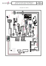
aiR  plus models (Usa-CanaDa)

Yellow / Green

Yellow / Green

Blue

Black

Brown

White

Black 
Blue

Schema elettrico stufe “AIR” versione America

MICROPROCESSORE

F

N

FUMI

   SCAMB.

COC.

ACC.

AL2

AL1

N

-TC1+

TERM.

N.AMB.

N.H2O

N.PEL.

ENC

+5V

GND

BLU

Condensatore

Red

Blue

Black Black

Green

Green

Green 

Brown

Blue

Blue

Black

Blue

Black

White

White

White

White

Green

Brown

Blue

Black

Brown Blue

Green Blue Black Brown

White

Brown

Blue Blue

Black

Black

Blue

Black

Brown

Blue

Blue

Blue

  Encoder

Red

Black

White

Brown 
Black 
Brown

Black

Brown

Blue

Microswitch

Mod.

DESCRIZIONE

Data

Dis.

Appr.

MODIFICHE

_

_

A3

(SCHEET)

FO

RMATO

----

ASSIEME COPERCHIO MONTATO

TOLLERANZ

E GENERALI PER QUOTE LINEARI, ANGOLARI, SMUSS

I E

RACCORD

I, CLASSE FINE UNI EN 22768-1, DOVE NON INDICATE

1:5

FCH

------------

SCALA

(SCALE

)

DENOMINAZIONE

(DENOMINATIO

N

)

MATRICE DI PIEGA

and must no

t be

 re

leased to oth

er parties without 

writte

n cons

ent 

any in

fring

ement 

in any way

 utilize

d fo

r the

 m

anifactur

e o

f the co

mpo

nent of unit her

ein 

illu

strated

All pro

prietary 

right re

serv

ed 

by Societ

y ECOT

ECK s.

r.l. This

 draw

ing 

shall not

 be reproduce

d or

ne venire c

omunicat

o a t

erz

i o 

ripr

odotto. La S

ocieta' pr

oprietaria 

tute

la i

 pr

opr

i

disegno non 

pot

ra' essere 

comunque utilizzat

o per la 

cost

ruzione dell' 

oggetto 

rap

pre

sentato

Proprieta' de

lla

 Societa' 

ECOTECK

 s.r.l.

 Senza aut

orizzazione s

citta della s

tess

a, il presente

MODIFICARE SOLO SU CAD

(CHECKED)

CONTR.

PESO Kg

DIS.

MA

TERIALE

(MA

TERIAL)

(DESIGNER)

DATA

(DATE)

C

A

D

 D

RAWNING H

A

NDLING ON

 CAD SYSTEM ONLY

MODELLO

TRATTAM. SUPERF

ICIALE

FLASH

Microswitch

NA

N

C

C

NA

N

C

C

DISP

LA

Y

PO

WER SWI

TCH

EXH

A

UST 

FAN

CA

PA

CI

TOR

CA

PA

CI

TOR

ROOM 

FAN 

SE

CO

N

D

A

RY

ROOM 

FAN 

IGNI

TOR

SAF

ET

Y

SWI

TCH

VA

CUUM SWI

TCH

A

UGER M

O

TOR

SMOKE P

ROBE

AMBIENT TEMP P

ROBE

SAF

ET

THERMOS

TA

T

(HOPPER)

SAF

ET

Y

SWI

TCH

27

Summary of Contents for Ecotek BOX LINE

Page 1: ...INSTALLER S MANUAL FOR FLOW LINE DESIGN LINE BOX LINE models Rev 1 for models with FLASH motherboard 01 NOV 6th 2008 For USA CANADA 110v 60 hZ F...

Page 2: ...n the hopper is filled 7 the pellets are loaded into the firepot 3 by means of the auger 1 Ignition takes place via the ignitor 2 that overheats the air coming from the inlet 5 which when in contact w...

Page 3: ...ATA DRWG NR N DISEGNO DATE CAD DRAWNING HANDLING ON CAD SYSTEM ONLY MODELLO MODEL TRATTAM SUPERFICIALE FLASH Microswitch NA NC C NA NC C CAPACITOR CAPACITOR ROOM FAN IGNITOR SAFETY SWITCH VACUUM SWITC...

Page 4: ...uction EXHAUST BLOWER Silicon dust shield Faston Laminar pack Blower ROOM AIR BLOWER ROOM AIR BLOWER Blade in self cleaning steel Capacitator Revs encoder connector Rotor bell Capacitator Blower Blowe...

Page 5: ...nector Flat cable connector 2 pole connector 2 pole connector ELECTRONIC MOTHERBOARD GEAR MOTOR Motor pack Rotor Faston electric connection Shaft Aluminium body DISPLAY FLAT CABLE Connects from displa...

Page 6: ...res the temperature of the room where the stove is installed You are advised not to rest the probe on the floor or against the wall If possible tie the probe with the power supply cable so that it doe...

Page 7: ...tomatic screw feeding 3 2 Modify SELECT RECEIPT 3 3 Pellet air blend setting 3 4 Rapid access menu 3 5 TIME CLEAR menu 3 6 FACTORY CALIBRATIONS menu 3 7 DATABASE menu 3 8 CLOCK SETTING menu 3 9 CHRONO...

Page 8: ...status of the external thermostat 7 2 2 Operating procedures with external thermostat 7 3 Table of thermostat settings AIR and BOX versions 8 0 Safety Switches 8 1 Safety Device for Auger when openin...

Page 9: ...nds after stove is switched ON the message shown in the following figure appears vER AIR Fig 1 vER BOX Fig 2 1 2 Initial conditions of a stove The starting modes of an Ecoteck stove are cold ignition...

Page 10: ...to start as soon as possible DISPLAY SHOWING WAITING FLAME in this phase while the resistance is still working loading of the pellet continues At this time the T1 reference value for reading the smoke...

Page 11: ...parameter pR 12 nO peLLet thReshOLD iMpORtant even if the smoke temp reaches the value set in the pR 15 the heat exchanger does not switch on until the stove goes to WORK mode this condition is neces...

Page 12: ...se THE DISPLAY SHOWS FINAL CLEAN The switch off button is pressed the pellet loading gear motor is switched off the exhaust blower goes to maximum power and the heat exchanger runs at power 5 When the...

Page 13: ...r34 Pr32 tempo max caricamento coclea PR33 T Lavoro Pr05 Pr02 es 7 Pt1 Pt3 Pt2 Pt impostata esempio pt3 Controllo incremento Pr34 Pr01 tempo max segnalazione MANCATA ACCENSIONE Pr31 Pr16 Pr17 Pr06 10...

Page 14: ...the restart threshold Tsmoke PR11 and in any case over PR13 SWITCH OFF PHASE the PR 39 timer switch ON RE IGNITION BLOCK After that time the stove goes into re ignition state if the smoke temperature...

Page 15: ...coclea PR33 T Lavoro Pr02 Pt1 Pt3 Pt2 Pt impostata esempio pt3 Controllo incremento Pr01 tempo max segnalazione MANCATA ACCENSIONE Pr31 Pr16 Pr17 Pr18 22 Pr23 27 Ventila Attesa Riavvio Max velocit Pr3...

Page 16: ...hOOse ReCipe When first installing a stove you can modify the pellet air blend to access the ReCipe menu hold button down 4 for 3 seconds then click button 4 until you reach menu 10 seLeCt ReCipes cli...

Page 17: ...istinguish its correct functioning To enter this menu proceed as follows 1 Keep button P4 pressed for 2 seconds CLOCK SETTING MENU will appear 2 Press button P4 4 times the display will show STOvE STA...

Page 18: ...TION OF THE STRINGS Description Values that can be set START PROG 1 From OFF to 23 50 in 10 steps STOP PROG 1 From OFF to 23 50 in 10 steps Day PROG 1 Between on off for days from Monday to Sunday POW...

Page 19: ...parameters in DEFAULT SETTINGS The parameter to be changed is PR42 the values change from OFF to 68 F Once the set room temperature is reached the stove as per default after about 4 minutes goes from...

Page 20: ...completely loaded with pellets N B Remember to empty the fire pot before igniting the stove Automatic auger feeding must be carried out only when the stove is in the OFF or FINAL CLEANING status 3 2 C...

Page 21: ...P1 and P2 to change the parameter value use keys P6 and P7 To exit the menu default settings press key P3 3 7 DATABASE MENU In processing phase 3 8 SET CLOCK menu To set the clock proceed as follows...

Page 22: ...equipped with radio wave palm remote controls and a receiver located on the right hand side of the stove Sometimes due to interference caused by other electric devices microwave ovens satellite decode...

Page 23: ...er the Pr35 time and can be canceled by pressing the P3 key 4 5 Pellets finished alarm This occurs if during the STABILISATION phase the smoke temperature does not reach the Pr12 value at the end of t...

Page 24: ...PR01 PR01 PR33 PR35 ANOMALOUS FLAME ALARM if SMOKE TEMP in Ti Ti 1 with rea ding error margin PR02 PR35 PELLETS FINISHED ALARM SMOKE TEMP PR12 PR12 BLACK OUT Black out time PR38 PR38 DEPRESSION ALARM...

Page 25: ...17 PR33 WORK 4 WORK After TIMER PR02 PR02 PR06 10 PR15 PR18 22 PR23 27 PR41 PR43 47 MODULATION 4 MODULATION WORKING if T AMB SET T AMB PR06 PR18 PR23 PR43 FIRE POT CLEANING 5 FIRE POT CLEANING With PR...

Page 26: ...ed the value set in the PR13 theTIMER PR40 T MIN EXTINCTION is activated in order to check that the flame has gone out completely IMPORTANT the TIMER mentioned above that can be set manually by the PR...

Page 27: ...ient probe and the ambient setting is handled by an ON OFF status of the external thermostat itself IMPORTANT Both in the AIR and the BOX versions to activate control via external thermostat connect t...

Page 28: ...IF TEMP SET ON DISPLAY IS HIGHER THAN AMBIENT PROBE CONTROL TEMP SET ON EXTERNAL THERMOSTAT EST EXTERNAL THERMOSTAT CONNECTED CONTROL ON THE AMBIENT PROBE For BOX versions MAN EXCLUDES EXTERNAL THERMO...

Page 29: ...pon delivery of each stove the hopper safety switch must be connected In no specific order please connect the wiring to these two prongs Fig B SPORTELLO PELLET 16 36 65 P3 wOrKing Fig A 8 2 SAFETY DEV...

Page 30: ...ECOTECK MATRICE DI PIEGA will be legally pursued diritti a rigore di legge and must not be released to other parties without written consent any infringement in any way utilized for the manifacture of...

Page 31: ...NON INDICATE 1 5 FCH SCALA SCALE DENOMINAZIONE DENOMINATION MATRICE DI PIEGA and must not be released to other parties without written consent any infringement in any way utilized for the manifacture...

Page 32: ...firmware used has the extension caf firmware for I023 motherboards this will be used on all new stove models divided into air box hydro and will be programmed according to the required usage Updates t...

Page 33: ...Brochure for models with FLASH motherboard firmware version ECT2008air ECT2008box PAGE 29...

Reviews: