Page 5
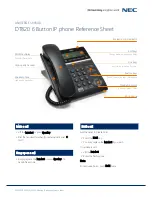
Step 6: Wiring the Emergency Phones to the SmartRescue
Use twisted, shielded, 22 or 24 AWG, 2 pair cable between the phones and the SmartRescue. The maximum
communication run is 5,100’.
Connecting Wire Run:
To SmartRescue:
Insert 4 wires for each phone as shown in
Diagram B
.
To Phone:
Wire out to a standard 2 pair RJ11 connector. Pins 2 and 3 (red and green) carry the outside phone line.
Pins 1 and 4 (yellow and black) are the intercom pair.
Diagram B
SmartRescue
NEUTRAL
120vac
HOT
Handset Connection
Dedicated Analog
Phone Line
24v Power Input
Battery Backup
Optional Sub-Master
Phone Ports
RJ11
Plug-In
Transformer
Phone Push Connector 1
Phone Push Connector 2
Phone Push Connector 3
Phone Push Connector 4
Phone Push Connector 5
Phone Push Connector 6
Phone Push Connector 7
Phone Push Connector 8
Phone Push Connector 9
Phone Push Connector 10
Supplied by
RATH®
Supplied by
RATH®
GROUND
Yellow (PIN-1)
Green (PIN-2)
Red (PIN-3)
Black (PIN-4)
L N -V +V
Wiring Emergency Phones to SmartRescue
Note:
When using the SmartRescue for Area of Refuge applications, it is recommended to use a biscuit jack for
connecting each phone. This will prevent loose connections that can cause the system to malfunction. Biscuit
jacks are available from RATH® by request.
Note:
DO NOT use aluminum conductors with push-in terminals.
Note:
Shields from the cabling runs (if used) should be attached to
one of the mounting screws on the SmartRescue housing.
Note:
Line impedance of the phone line is 600 ohms.
Step 7:
Mount the front cover back on to the enclosure.
Emergency Phone
Yellow (PIN-1)
Green (PIN-2)
Red (PIN-3)
Black (PIN-4)
Page 4
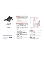
Diagram B
0
2
5
3
1
4
6
7 8 9
*
#
0
2
5
3
1
4
6
7 8 9
*
#
0
2
5
3
1
4
6
7 8 9
*
#
0
2
5
3
1
4
6
7 8 9
*
#
0
2
5
3
1
4
6
7 8 9
*
#
2 Pair- Twisted
24-22ga
2 Pair- Twisted
24-22ga
2 Pair- Twisted
24-22ga
2 Pair- Twisted
24-22ga
2 Pair- Twisted
24-22ga
1 Pair Wire
From Telco
Plug-In
Transformer
GROUND
120vac HOT
NEUTRAL
GROUND
120vac HOT
NEUTRAL
GROUND
120vac HOT
NEUTRAL
GROUND
120vac HOT
NEUTRAL
GROUND
120vac HOT
NEUTRAL
SUB-MASTER 1
SUB-MASTER 2
OPERATION:
1.
SOLID LIT
LED
(PHONE, SUB-MASTER
OR RESCUE SERVICES) INDICATES
CALL IN PROGRESS.
2.
SLOW BLINKING
LED
INDICATES
CALL ON HOLD.
3.
LIFT HANDSET.
4.
PRESS YELLOW
TALK/HOLD
BUTTON TO CALL
IN TO A SPECIFIC SUB-MASTER. IF THE GREEN
LED
IS LIT YOU WILL JOIN CONVERSATION.
5.
PRESS BLACK
TALK/HOLD
BUTTON TO CALL IN
TO A SPECIFIC PHONE. IF THE GREEN
LED
IS
LIT YOU WILL JOIN CONVERSATION.
6.
PRESS
TALK/HOLD
BUTTON AGAIN TO PLACE
CONVERSATION ON HOLD.
7.
PRESS RED
DISCONNECT CALL TO RESCUE
SERVICES
BUTTON TO END EXTERNAL CALL.
ANY PHONE AND SUB-MASTER ORIGINALLY
TALKING REMAIN IN CONVERSATION WITH
THIS UNIT.
8.
HANG UP HANDSET TO END CALLS TO PHONE
AND SUB-MASTER.
BATTERY
POWER
PHONE 1
PHONE 2
PHONE 3
PHONE 4
PHONE 5
DISCONNECT
CALL TO
RESCUE
SERVICES
SMARTRESCUE PHONE - 5
READ ALL OPERATING STEPS
BEFORE PROCEEDING
RESCUE SERVICES
SOLID LIGHT: CALLING
BLINKING LIGHT: RECEIVED
EMERGENCY PHONE
SOLID LIGHT: CALLING
BLINKING LIGHT: RECEIVED
EMERGENCY PHONE
SOLID LIGHT: CALLING
BLINKING LIGHT: RECEIVED
EMERGENCY PHONE
SOLID LIGHT: CALLING
BLINKING LIGHT: RECEIVED
EMERGENCY PHONE
SOLID LIGHT: CALLING
BLINKING LIGHT: RECEIVED
EMERGENCY PHONE
24/5VA
24/5VA
24/5VA
24/5VA
24/5VA
Wiring Diagram with Individual Transformers
N56W24720 N. Corporate Circle • Sussex, WI 53089
800-451-1460 • www.rathcommunications.com
12/21
Twisted, Shielded
Wire Recommended