background image

Volume 

Adjust 

VR1

Mic 

Sensitivity 

VR2

Page 12

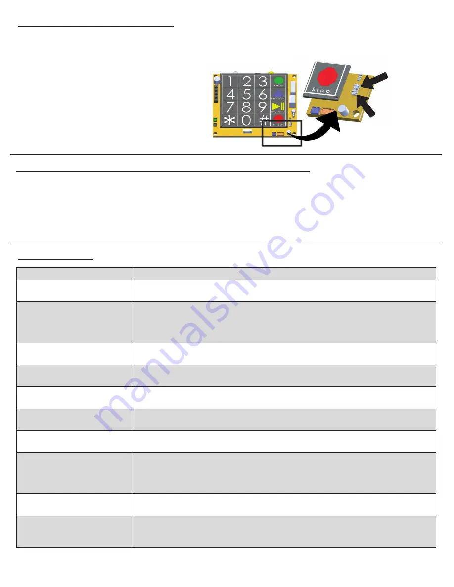
Adjusting Volume on SmartPhone

1.

 Locate the silver VR1 POT on the bottom right corner of the SmartPhone board

2.

 Using a fine Philips Head screwdriver, turn the VR1 clockwise to increase the volume and counterclockwise to 

    decrease the volume

3.

 The VR2 POT adjusts the microphone

Troubleshooting

Problem

Possible Cause & Solutions

Power LED is not 

illuminated:

 Check to make sure the power being used has 24v going into the phone.

• Make sure power connection on the circuit board is secure.

Battery LED is not illuminated 

or always shows red:

 Battery has not charged for long enough. Wait 18 hours for the battery to trickle

  charge. When fully charged it will have 19v.

• Battery plug is not connected to circuit board. Verify connection.

• Battery is worn. It is recommended to replace the battery every 2 years.

LEDs on SmartPhone flash 

when button is pressed:

 Verify the phone line is working and is connected properly.

• Verify dial tone is present at the phones.

Sub-Master and phone LEDs 

blinking on SmartRescue:

 Verify power is applied and the backup battery is connected properly to the 

  SmartRescue board.

SmartRescue LEDs stay on:

 Wires may be crossed. Verify wiring from the SmartRescue to the SmartPhone is  

  correct.

Two-way communication from 

SmartPhone is poor:

 There could be feedback on the line. Adjust the VR1 and VR2.

• Verify wiring is not spliced onto the phone line cord.

SmartRescue will not dial 

phones:

 Verify intercom wires (yellow and black) are connected properly from the   

  SmartRescue to the SmartPhones. They should be on pins 1 and 4.

SmartRescue will dial phone 

but phones will not dial 

SmartRescue:

• No outside phone line connected to SmartRescue.

• Phone line connected does not have working 24v to 52v.

• Line connected has voltage but does not have working dial tone.

• Plug analog phone into phone line and place a call out to verify line.

No sound or tone on 

SmartRescue handset:

 Verify 24v power is connected to the SmartRescue.

 Verify that the volume dial on handset is not turned down.

Dial tone is present on 

SmartRescue handset and 

phone is not calling out:

 There should not be a dial tone on the SmartRescue handset.

• Wire pairs are out of order. Verify wire pairs are connected to the correct pins.

• Wires are shorted and need to be replaced.

Change Frequency of Phone Line Check using Onboard Keypad

1.

 Press 

ENTER

 to begin programming

2.

 Press 

3, 4, ENTER,

 4 digit number in HH:MM 

Example:

 0020 = 20 minutes, 2300 = 23 hours

Note:

 The longest line check is once every 23 hours. The default setting is 10 minutes. To comply with UL 2017, 

the time must be set to 3 minutes.

3.

 Press and hold 

STOP

 for 3 seconds to exit programming

Summary of Contents for 2500-205D

Page 1: ...SmartRescue 5 10 Installation Operations Manual N56W24720 N Corporate Circle Sussex WI 53089 800 451 1460 www rathcommunications com RP8500510 Ver 4 11 19 WARRANTY 2YEAR...

Page 2: ...ations com Table of Contents SmartRescue 5 10 Installation Powering the SmartRescue Wiring Emergency Phones to SmartRescue Typical Wiring Diagrams for Elevators Typical Wiring Diagram for Areas of Ref...

Page 3: ...s Pre Installation Requirements Step 1 Remove the front cover from the SmartRescue and mount the SmartRescue back box to the wall using suitable mounting screws not included Step 2 Punch out the condu...

Page 4: ...d 120vac outlet Option 2 Hard Wired Transformer Connect the hot wire of the 120vac to the L screw Connect the neutral wire of the 120vac to the N screw Connect the ground wire of the 120vac to the gro...

Page 5: ...phone line is 600 ohms Step 7 Mount the front cover back on to the enclosure Emergency Phone Yellow PIN 1 Green PIN 2 Red PIN 3 Black PIN 4 Diagram B 0 2 5 3 1 4 6 7 8 9 0 2 5 3 1 4 6 7 8 9 0 2 5 3 1...

Page 6: ...SPECIFIC PHONE IF THE GREEN LED IS LIT YOU WILL JOIN CONVERSATION 6 PRESS TALK HOLD BUTTON AGAIN TO PLACE CONVERSATION ON HOLD 7 PRESS RED DISCONNECT CALL TO RESCUE SERVICES BUTTON TO END EXTERNAL CAL...

Page 7: ...HOLD 7 PRESS RED DISCONNECT CALL TO RESCUE SERVICES BUTTON TO END EXTERNAL CALL ANY PHONE AND SUB MASTER ORIGINALLY TALKING REMAIN IN CONVERSATION WITH THIS UNIT 8 HANG UP HANDSET TO END CALLS TO PHON...

Page 8: ...VED EMERGENCY PHONE SOLID LIGHT C ALLING BLINKING LIGHT RECEIVED EMERGENCY PHONE SOLID LIGHT C ALLING BLINKING LIGHT RECEIVED EMERGENCY PHONE Typical Wiring Diagram for Area of Refuge Applications 1 P...

Page 9: ...rgency Number as entered in b Stop 4 To exit program mode press and hold Stop for 2 3 seconds until warble sound Program the Location Message Note This is always done unless your Call Center requests...

Page 10: ...hone that placed the call c If call is not answered at the SmartRescue the Emergency Phone will hang up and dial the second number programmed into the phone d The Rescue Services LED located next to t...

Page 11: ...6 9 TB1 Relay SmartRescue System Activation Relay When an Emergency Phone has been activated this relay changes from NO to closed It can be connected to a strobe or other notification means Connectio...

Page 12: ...SmartPhone is correct Two way communication from SmartPhone is poor There could be feedback on the line Adjust the VR1 and VR2 Verify wiring is not spliced onto the phone line cord SmartRescue will n...

Page 13: ...or indoor use only Operating temperature 32 F to 120 F 0 C to 49 C TB1 Relay Load Current 130mA Load Voltage 350vdc or vac Note Input power circuit battery circuit and phone circuits are supervised in...

Page 14: ...61 294 96 1 03 26 25 1 27 32 38 0 32 8 05 0 88 22 23 4 34 110 17 0 45 11 41 0 50 12 70 1 0 56 319 09 11 61 294 96 0 33 8 49 5 81 147 48 0 28 7 18 FRONT PANEL COVER LEFT SIDE BOTTOM SIDE CONTROL INSIDE...

Page 15: ...ED Y G R B Y G R B Y G R B Y G R B Y G R B Y G R B Y G R B Y G R B Y G R B Y G R B 1 2 3 4 5 6 7 8 9 10 HOOK SWITCH Y G R B Y G R B 0 69 17 50 0 84 21 27 0 69 17 46 0 69 17 46 0 25 6 35 0 13 3 18 4 02...

Reviews: