background image

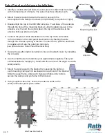
Mounting Bracket

Solar Panel Clamps

Slots for 

Hose Clamps

 pg.  3

Solar Panel and Antenna Installation:

C O M M U N I C A T I O N S

E M E R G E N C Y

866-850-8854      www.rathsecurity.com

1.  Identify a location that will allow the solar panel to collect maximum light 

     with minimal amount of shade. The panel must face directly south.

2.  Mount the solar panel bracket to the wall or pole with the 

     two supplied hose clamps or screws (not provided). (see photo on right)

3.  Disassemble the top of the 900 MHz antenna.  Feed base of the antenna 

     through the hole of the mounting bracket, slide the plastic sleeve of the 

     antenna over the bolt, then screw down the top of the antenna to the 

     antenna bolt (see photo on right).

4.  Connect the power cable that leads out of the top of the call station

     to the terminals in the solar panel electrical box by feeding the wire

     through the circular opening in the box. Connect red to positive and black 

     to negative which are the outer two terminals. 

    (see picture below, Solar Panel Electrical Box) 

5.  Secure the weather-tight connection to box and reattach cover by installing

     the screw(s).

6.  Use the chart below to determine your approximate longitude. Take your

     estimated latitude, multiply by .9 and add 29 to arrive at the angle to set the

     solar panel to.

7.  Mount the solar panel to the bracket by loosening the bolts on 

     each mounting clamp which are located on each end of the bracket.

     Slide the panel frame under each clamp and tighten the bolts to 

     secure the clamps and pin frame to the bracket. 

8.  Using supplied cable ties, secure the antenna cable to the 

     solar panel solar panel power cable.

Solar Panel Electrical Box

Feed Power 

Cable

thru here 

Red 

Wire

Black

Wire

Antenna

Summary of Contents for 2100-CS9

Page 1: ...rations Manual C O M M U N I C A T I O N S E M E R G E N C Y N56 W24720 N Corporate Circle Sussex WI 53089 866 850 8854 262 246 4828 fax www rathsecurity com 11 10 Made in the USA 2 Year Warranty 2100...

Page 2: ...gency communication systems you can rely on Rath to continually provide Innovative Thinking Design and Value Thank you for your business Tom Touchett President Parts Listing Call Station Installation...

Page 3: ...all battery in bottomof call station 8 Connect the power cables to the battery Red to positive and black to negative 9 Slide the Photocell cover to the proper position on the photocell in order for th...

Page 4: ...the top of the call station to the terminals in the solar panel electrical box by feeding the wire through the circular opening in the box Connect red to positive and black to negative which are the o...

Page 5: ...ogram Emergency Numbers A Press 1 Enter phone number Stop Note Press 2 5 in step 2A for Emergency numbers 2 5 as needed Step 4 If Ring Down No dial tone Skip Step 3 above A Press 1 Enter Pause Stop B...

Page 6: ...ne number Wait for confirmation tones Note Emergency numbers 2 5 Repeat Step 2A pressing 2 5 as needed Step 3 If Ring Down No dial tone Skip Step 2 A Press 1 Wait for confirmation tones B Press 9 0 Wa...

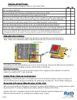
Page 7: ...ce of the Unit Rath recommends that the Emergency Call Station be tested and maintained on a monthly basis to ensure proper operation For testing follow the procedure outlined in Testing of the Phone...

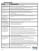
Page 8: ...a sunny day If voltage is low or 0 the panel may be damaged Solar Station appears non functional Strobe does not flash and no audio is heard from speaker when button is pushed Check to make sure phone...

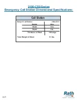
Page 9: ...nsional Specifications Body of Call Station 2100 CS9 Total Weight of Steel 51 lbs Height Width Depth Thickness of Steel 36 in 10 in 8 in 18 Gauge Call Station pg 8 C O M M U N I C A T I O N S E M E R...

Page 10: ...der this warranty shall be solely limited to the repair or replacement of the defective parts within the warranty period and will not be liable under any circumstances for consequential or incidental...

Reviews: