background image

Summary of Contents for DM25

Page 1: ... G ra DIGITAL MULTIMETER OPERATOR S MANUAL ...

Page 2: ...nformation 1 1 Preliminary 1 2 During Use 1 3 Symbols 1 4 Maintenance 2 Description 3 Operating lnstruction 3 1 Measuring Voltage 3 2 Measuring Current 3 3 Measuring Resistance 3 4 Testing Diode PAGE 1 1 2 3 4 5 I 9 I 10 11 ...

Page 3: ...3 5 Testing Transistor 3 6 Continuity Test 4 Specifications 5 Accessories 5 1 Supplied with the meter 5 2 How to use the holster 6 Battery Fuse Replacement t2 12 13 20 20 20 22 ...

Page 4: ...safely and is kept in good operating condition 1 1 PRELIMII ARY r When using the meter the user must observe all normal safety rules concerning Protection against the dangers of electrical current Protection of the meter against misuse o Full compliance with safety standards can be guaranteed only if used with test leads supplied lf necessary they must be replaced with the same model or same elect...

Page 5: ... at the highest Position o Before rotating the range selector to change functions disconnect test leads from the circuit under test oWhencarryingoutmeasurementsonTVorswitchingpowercircuits alwaysrememberthat there may 0 nign amplitude voltages pulses at test points which can damage the meter o Never perform resistance measutements on live circuits o Always be careful when working with voltages abo...

Page 6: ...s be sure that leads have been disconnected from any measurement circuits Components should not be connected to the hFE socket when make in voltage measurements with test leads CAT ll maximum voltage between terminals and earth is 1000V when used on local level i e appliances portable equipment etc CAT lll maximum voltage between terminals and earth is 60OV when used on distribution level i e fixe...

Page 7: ...nly with the specified voltage and current ratingsr F1 F 2AI25OY F2 F 1OA 250V r lf any faults or abnormalities are observed the meter can not be used any more and it has to be checked out o Never use the meter unless the back cover is in place and fastened fully o To clean the meter use a damp cloth and mild detergent only do not use abrasives or solvents on it ...

Page 8: ...unctions DC voltage measurement 5 ranges from 2OOrnV to 1000V AC voltage measurement 5 ranges from 2OOmV to 70OV DC current measurement 7 ranges trom 2OpA to 1OA Ac current measurement 6 ranges from 200pA to 10A Resistance measurement 7 ranges from 2OOo to 200MO Diode test Transistor test Audible continuity test 5 ...

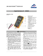
Page 9: ...1 Power Switch 2 LCD Display 3 Transistor Testing Socket 4 Rotary Switch 5 V O lnput Jack 6 COM lnput Jack 7 A lnput Jack 8 10A Input Jack ...

Page 10: ...o extend the battery life Auto Power Off function is provided Optional The meter will be turned off automatically within around 4O minutes To turn on the meter again push the power switch to release it and then push it once more 2 3INPUT JACKS This meter has four input iacks that are protected against overload to the limits During use connect the black test lead to the COM jack and the red test le...

Page 11: ...ection lnout Limits 2OOmV v v o n t A I A 10A vta vta vta vta A 10A 250V dc or rms ac 1000V dc or 7O0V rms ac sine 25OV dc or rms ac 25OV dc or rms ac 2A dc or rms ac 1OA dc or rms ac Current ranges are protected by fuses 8 ...

Page 12: ... the source or load under measurement 3 Read LCD display The polarity of red connection will be indicated when making a dc measurement 4 When only the figure 1 is displayed it indicates overrange situation and the higher range has to be selected 3 2 MEASURING CURRENT 1 Connect the black test lead to the COM jack and the red test lead to the A iack for a maximum of 2A For a maximum of 1oA move the ...

Page 13: ...it indicates overrange situation and the higher range has to be selected 3 3 MEASURING RESISTANCE 1 Connect the black test lead to the COM iack and the red teas lead to the V O jack NOTE The polarity of the red lead connection is positive l 2 Set the rotary switch at desired o range position and connect test leads across the resistance under measurement Read LCD display NOTE 1 For resistance above...

Page 14: ...sults For example when measuring 100M O resistance the reading will be 1O1 0 and the correct measuring result should be 1O1 0 1 O 1OO OMO 3 4 TESTING DIODE 1 Connect the black test lead to the COM jack and the red test lead to the V O iack NOTE The polarity of red lead connection is positive l 2 Set the rotary switch atll position and connect the red lead to the anode the black lead to the cathode...

Page 15: ...ing socket on the front Panel s lcD iisplay will show the approximate hFE value at the test condition of base current 1OpA and Vce 3 2V 3 6 CONTINUITY TEST 1 Connect the black test lead to the COM iack and the red test lead to the V O jack 2 Set the rotary switch at t position and connect test leads across two points of the circuit under testing lf continuity existsli e resistance less than about ...

Page 16: ...Earth Ground Fuse Protection Power Supply Display Measuring Method Overrange lndication Polarity lndication Low Battery lndication Operating Temperature 1OOOV dc or 70OV rms ac sinel A F 2Al250V 1OA F 1OA 250V 9V battery NEDA 1 604 or 6F22 LCD 1999 counts max updates 2 3lsec Dual slope integration A D converter l displayedonly displayedautomatically E displayed ooC to 4OoC 32oF to 104oF 13 ...

Page 17: ...o t22oFl 91 x 189 3 1 5 mm 31 Og lncluding batterY Range Resolution Accuracy 2OOmV 0 1mV O 5olo of rdo 1 diOits 2V 1mV f O 5olo of rdg t 1 digits 20v 1OmV 0 5olo of rdq t 1 digits 200v 0 1v t O 5 of rdq t 1 diqits 1 000v 1V t 0 8 of rdg t 2 digits lnput lmpedance lOMO 14 ...

Page 18: ... to 4OOHz Response Average calibrated in rms of sine wave Range Resolution Accuracy 2OOmV O 1mV L 1 2o o of rdq t 3 digits 2V 1mV t 0 806 of rdq t 3 diqits 20v lOmV 0 806 of rdq 3 diqits 200v o 1v 1 O 8olo ol rdo 3 diqits 700v 1V 1 2o o of rdo 3 diqits 15 ...

Page 19: ...luA O 8 of rdg 1 diqits 1 OmV sA 2mA 1uA O 8o o of rdo 1 dioits 100mV mA 2OmA lOzA O 8olo of rdq 1 dioits 1 lmV mA 200mA O 1mA l 5o o of rdo 1 dioits 2 0mV mA 2A lmA 1 5o o of rdg 1 diqits o 4v tA 10A lOmA 2 Oo o of rdq 5 dioits 0 03v A overload Protection F 24 fuse tor2oyA to 2A ranges F 1oA fuse for 1oA range 16 ...

Page 20: ...rage calibrated in rms of sine wave Range Resolution Accuracy Burden Voltaoe 2OOpA O 1zA l 8o o of rdo t 3 diqits 1 OmV rrA 2mA 1uA 1 Oo o of rdo t 3 diqits IOOmV mA 2OmA 10zA 1 Oo o of rdo 3 dioits 11mV mA 200mA O 1mA 1 8o o of rdq t 3 diqits 2 OmV mA 2A 1mA 1 8o o of rdq t 3 diqits o 4v A 10A lOmA t 3 Oolo of rdq 7 diqits 0 03v A t7 ...

Page 21: ...o This 1Mo should be 1g _ subtracted from measurement results Ranqe Resolr tin Accuracv 200c o 1rl t 0 8 of rdg 3 digits 2ka 1c r 0 8 of rdg 1 digits 20ko 100 t O 8 of rdg 1 digits 200kf 1000 t 0 8 of rdg 1 digits 2MO 1ko t 0 8 of rdg 1 digits 20MO 1oko 1 Oo o of rdg 2 digits 200MO 1 00ko t 5 Oolo of rdg 10 digits t 10 digits ...

Page 22: ...CONTINUITY Range Descriplion Test Condition f Shows the approximate forward voltaqe droP Forward Current 1mA Vce 3 2V Range Description n Buih in buzzer will sound if the resistance under test is less than about 7OO ...

Page 23: ...T 60 Operating Manual Holster 5 1 HOW TO USE THE HOTSTER The holster is used to protect the meter and to make the measurement more comfortable lt comes with two stands installed together The following figure shows how to use the holster to a Support the meter with a standard ar le b Support the meter with a small angle using the little stand 20 ...

Page 24: ...c l rtr ilE meter on the wall using the little stand Tfte fte fittle stard off frorn the back side of the large stand ard insert it into holes located upDer on the holster d Hold test leads N f ...

Page 25: ...ys as a result of the operator s error Open the case as mentioned above and take the PCB assembly out from the case Replace the blown fuse with ratings specified Iwanrruc Before attempting to open the case be sure that test leads have been disconnected from measurement circuit to avoid electric shock hazard For protection against fire replace fuses only with specified ratings F1 F 2A 25OY F2 F 1OA...

Reviews: