background image


Next,


we


wire


the


LED


strings


(jumpers)


to


the


appropriate


wires


on


the


drivers


for


your


kit.


Last,


tuck


the


wires


neatly


underneath


the


heatsink.


Wiring


the


Aurora


LED


Array


to


Drivers


The


Aurora


LED


Array


is


compatible


with


many


driver


choices.


Contact


RapidLED


with


any


questions


not


covered


by


this


document.


Included


below


are


instructions


for


using


Mean


Well


LPC,


LDD,


and


RapidLED


Nano


drivers.


We


do


not


recommend


using


any


type


of


switches/quick


connects


on


the


DC


(LED)


portion


of


the


set

up.


***

DO


NOT


APPLY


POWER


TO


ANY


COMPONENTS


BEFORE


ALL


CONNECTIONS


AND


WIRING


ARE


COMPLETE


OR


YOU


RISK


BURNING


OUT


THE


LEDs


IN


YOUR


ARRAY(S)

.***


We


will


use


the


hole


where


the


5


wire


cable


is,


so


remove


this


cable


from


your


hood.


Run


the


red


and


black


driver


jumpers


for


each


string


through


this


hole


to


outside


of


the


hood.


Mean


Well


LPC


Drivers


(Skip


if


you


have


any


other


driver):


For


LPC


drivers,


use


wire


nuts


to


connect


the


V+


from


a


driver


to


the


first


red


wire


of


the


driver


jumper


for


the


first


channel.


Then


connect


the


V

‐ 

from


the


same


driver


to


corresponding


black


wire


on


that


driver


jumper.


Repeat


for


the


other


3


drivers


and


driver


jumpers.


Summary of Contents for Coralife BioCube 29 Aurora Array Retrofit

Page 1: ...DD Drivers to Power Supply 22 Connecting LDD Drivers to LED Strings 23 Finishing Up 24 Overview As with any type of lighting retrofit there are many dangers difficulties and pitfalls that may occur The Rapid LED Coralife BioCube 29 retrofit should only be attempted by people familiar with AC power and wiring electronics LEDs LED Drivers series circuits and be comfortable with the fact that this re...

Page 2: ... you must remove three fasteners from the rear of the hood to get it off of the tank We found it easiest to insert a hex wrench into one side of the fastener and gently tap laterally with a hammer until it releases The fasteners release easily little power is required Repeat this for all three and remove the hood from the tank After the hood is removed unscrew and remove the plastic cover that pro...

Page 3: ...tor and LED sockets from the hood Reflector removal requires unscrewing the two metal fluorescent bulb holders and the LED strip socket in the middle of the hood The reflector should lift out easily Cut the green grounding wire from the hood to completely remove it ...

Page 4: ...rews as indicated by the arrows in the photo below unclip and remove the sockets Ballast Removal The end goal of this section is to remove the ballasts and the right side AC line in two power cords from the hood We will be left with one original power plug that will power the original fans Removing the ballasts requires cutting an AC line in To avoid any problems double check and confirm all power...

Page 5: ...fications on this step be and look different depending on manufacturer modifications out of our control Keep in mind the actual goal of the step as opposed to the photos To begin with the hood facing up with the back of it nearest your body cut the AC line and neutral wires coming from the rightmost ballast If you cannot locate them the ballast has a wiring diagram on its label indicating ACL and ...

Page 6: ...Next strip and tightly cap the AC wires cut from the ballast with wire nuts ...

Page 7: ...Next unclip the power connector for the left ballast ...

Page 8: ...h ballasts from the hood There are two screws per ballast Transformer Removal To remove the transformer on the right we first unplug it from the circuit board Simply unplug the two wires from their sockets in the lower right hand corner of the picture below ...

Page 9: ...amage the components or hurt yourself in this step the connections can be very tight and difficult to remove Please note that we will leave 4 connections as is which will switch the fans on and off Next we remove the transformer on the right Simply remove the two screws and remove it from the hood ...

Page 10: ...from the right side of the hood First unscrew the strain relief holding down the right side power cords Next cut the ends off of the cords and pull them out of the hood Replace the strain relief unscrewed in the above picture and replace the rubber grommet the AC inlet wires were removed from ...

Page 11: ...Prepared Hood Your prepped hood should look like the one below You should be able to plug it in and switch the fans off and on ...

Page 12: ...bosses from the hood in which case you will have to attempt repair with super glue For this retrofit it is easiest to line up one of the rearmost screws and screw it in first Next rotate the heatsink around this screw until you can drop the other three rear screws into their mounting holes Be patient they will line up Once they line up screw them all in Note the two screws furthest from the rear o...

Page 13: ...After the four bottom screws are snugly affixed screw in the top two screws Ensure you do not make them too tight Over tightening the top two screws may warp your hood and then the cover won t fit ...

Page 14: ...te o UV 700mA max 4 SemiLEDs Violet UV Wiring the Aurora Puck In this step we will connect the driver jumpers and terminal plugs to the array First insert 4 terminal plugs into the 2 pin sockets on the edge labeled Connect to second array or Plug before Applying Power They will snap in and be difficult to remove if fully inserted Give them a little tug monkey tug not gorilla tug to ensure they do ...

Page 15: ...jumper into each of the 2 pin sockets on the edge labeled with the colors Blue Color White and UV As with the terminal plugs these should snap in and not fall out Give them a gentle tug monkey tug not gorilla tug and ensure they do not fall out ...

Page 16: ...sink To attach the Aurora LED Array to the heatsink we will use screws with a small bit of thermal grease under the puck with the following 4 holes The array will look like this on the heatsink again your heatsink may be anodized green ...

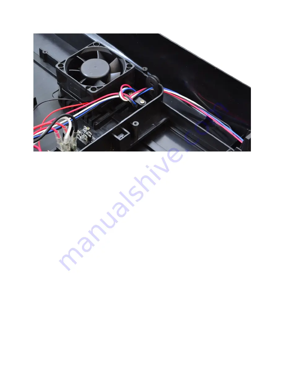
Page 17: ...ver jumpers and run that through the empty space left from removing some of the power cords We start by running our wire through the void left by one of the cut power cords Next we run it through the rubber grommet separating the interior of the protected hood from the exterior Tie a loose knot around the strain relief post to prevent damage to internal components if the outer wires get pulled too...

Page 18: ... DC LED portion of the set up DO NOT APPLY POWER TO ANY COMPONENTS BEFORE ALL CONNECTIONS AND WIRING ARE COMPLETE OR YOU RISK BURNING OUT THE LEDs IN YOUR ARRAY S We will use the hole where the 5 wire cable is so remove this cable from your hood Run the red and black driver jumpers for each string through this hole to outside of the hood Mean Well LPC Drivers Skip if you have any other driver For ...

Page 19: ...ed moisture resistant wire nuts Order is not important because AC current alternates Obviously this step is dangerous because you are working with 120AC current Make sure nothing is plugged in and have a licensed electrician assist you with this step RapidLED Nano Drivers with Potentiometer Skip if you have any other driver Using a screwdriver remove the cover screws from the right side of the Nan...

Page 20: ...inal screw until the wire the terminal when lightly tugged on Repeat with the black driver jumper wire and the V terminal screw If you are using an 0 10V analog controller ie Apex instead of the potentiometer you will repeat these steps for the D and D terminal to remove the potentiometer and to insert the positive and negative dimming wires from the controller Consult the controller s documentati...

Page 21: ...the right side of the SE 350 48 power supply insert the wires into the proper screw terminals and tighten the screws The green wire must go to ground as pictured below The white wire should go to N and the black to L NOTE If you are using AC power other than 100 120VAC there is a switch on the side of the power supply that must be flipped or you will damage the power supply ...

Page 22: ...ower Supply Next loosen a screw on the V and V areas of the power supply The red Vin wire goes to a V screw on the power supply and the black Vin wire goes to a V screw on the power supply Insert wires and tighten the screws ...

Page 23: ... the Blue and White channels ONLY and the LDD 700HW drivers will be used on the UV and Color channels due to the current limitations of each channel If you are using a PWM controller connect your controller to the white Dim wire Other connections might be necessary so consult your controller s instructions on this wiring The LDD drivers are only compatible with a controller that outputs a 0 5V PWM...

Page 24: ...Finishing Up After all of your wiring is complete re attach the plastic cover power it up and enjoy ...

Reviews: