


7
3 Display Operation
3.1
Startup
When power is applied, the unit will begin with a LED segment test, followed by the software date,
which is displayed for 2 seconds. Next, saved configuration settings are loaded from the non-volatile
EEPROM. By default, the TDD2 attempts to detect a MTS G-Series sensor and displays “GSErIE” if one is
found (see section 4.3.1 for information on sensor auto-detection). The display then begins normal
operation: interrogating the transducer and displaying the returned position on the LED display.
3.2
Normal Operation
During normal operation, the sensor is interrogated for magnet position information once every 5-
milliseconds. The display is updated with new position information at the user defined display update rate.
An interactive front-panel setup menu can be entered during normal operation. Position updates
continue during use of the setup menu.
3.2.1
Error Messages
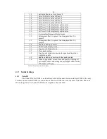
If an error condition is detected during normal operation, an error message will be displayed in lieu
of the position. Table 5 shows the possible error messages.
Error Condition
Displayed Error Message
No Error
Position Displayed
Working transducer, no magnet
No transducer or magnet
Table 5: Error Messages
3.3
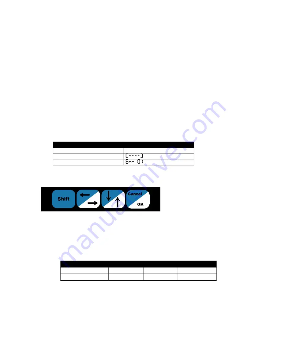
The Front Panel
The front panel has four
switches labeled (left to right): ‘Shift’,
‘Right/Left’,
‘Up/Down’,
and
‘OK/Cancel’. Figure 1 shows the layout
of the switches. These switches are used
for operator control of the display and
navigation of the front panel menu. The
Right/Left, Up/Down, and OK/Cancel switches each have two functions, depending on whether the Shift
switch is pressed at the same time. Error: Reference source not found6 shows the key press resulting from
pressing the switches with and without the Shift switch.
In this manual, a reference to a full switch name, such as “the OK/Cancel switch,” refers to the
switch itself. A reference to a keypress, such as “the Down key,” refers to the action required to activate that
key press (pressing the Shift switch and the Up/Down switch).
3.3.1
Entering the Front Panel Menu
Pressing and holding the Right/Left and Up/Down switches simultaneously for 2 seconds enters the
front panel menu. See section 3.3.3 for information on navigating the menu and section 4 for information on
setup items available in the front panel menu.
Right/Left
Up/Down
OK/Cancel
Output Without Shift
Right
Up
OK
Output With Shift
Left
Down
Cancel
Table 6: Shifted Switch Output
Figure 1: The Front Panel Switches


