12
4.2.9
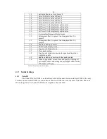
Displayed Gap
The
displayed gap
is used when the display mode is set to
gap
, and indicates an adjacent set of
magnets. Examples: Gap 1 is the distance between magnets 1 and 2, Gap 4 is the distance between magnets
4 and 5.
4.2.10 Single-Magnet Fallback
If the display mode is set to Gap or Relative, the display will normally show a no magnet error if
only 1 magnet is detected. However, changing the Single-Magnet Fallback setting to 'Yes' will cause the
TDD2 to act as if the display mode was set to Single when only one magnet is present.
4.2.11 Reference Magnet
The position of the reference magnet is subtracted from the position of the displayed magnet in
relative mode. In any other display mode, this has no effect.
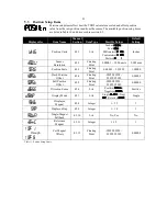
4.2.12 Per Magnet Offsets
Each magnet can have a unique offset, in addition to the shared hard and soft offsets. See section
3.4 for information on how position is calculated.
4.3
Transducer Settings
Transducer settings configure the interface to the sensor.
4.3.1
Transducer Auto-Detection
The TDD2 supports three auto-detection modes: G-Series, Standard, and Off. The G-Series auto-
detection is able to detect MTS G-Series transducers. At startup, the TDD2 will automatically detect if a G-
Series transducer is attached and obtain the transducer type (Start/Stop, PWM), gradient, and number of
recirculations directly from the sensor. If a G-Series sensor is not detected, operation will continue as if the
auto-detection mode was set to none.
The Standard auto-detection is able to detect non-G-Series PWM and Start/Stop protocol
transducers. At startup or when no transducer is detected, the TDD2 will detect and change the transducer
type setting to the type of transducer attached. The position will then display normally. If the TDD2 loses
connection to the sensor, auto-detecting will begin again.
Setting auto-detection to Off disables the auto-detection features of the TDD2.
Parameters changed due to auto-detection are not saved automatically, and if it is desired to retain
the settings (i.e. if auto-detection will be turned off), they must be saved manually. The default auto-
detection mode is G-Series, but will not hinder normal operation if a G-Series transducer is not found.
4.3.2
Transducer Type
The transducer type is the type of sensor that is currently being interrogated. The TDD2 can
support PWM, Start/Stop, MTS CANbus protocol, SSI Binary, SSI Gray Code, and externally interrogated
SSI binary output sensors. SSI Binary transducers output position data in binary format with the most
significant bit first. SSI Gray code transducers output position information using a binary reflected Gray
code in which all adjacent numbers differ by only one bit. The default transducer type is SSI Binary.
4.3.3
Number of Magnets
CANbus and Start/Stop transducers can return position information for more than one magnet. For
these types of sensors, the number of magnets configuration value determines the expected number of
magnets on the transducer. For other types of sensors, this value should be set to 1. The default number of
magnets is 1.
4.3.4
SSI Word Length
If a SSI sensor is selected, the number of bits of data transferred from the sensor can be
configured. Most magnetostrictive transducers provide 24 or 25 bits of position information, but values
from 8 to 32 bits are supported by the TDD2. If this number is not set correctly, the apparent resolution of
the sensor will be halved for each bit that is ignored; the resolution will appear to double for each bit that is
interpreted by the TDD2 but not output by the sensor. The default word length is 24 bits.


