background image

Adjustment of the projector focus 

During the scanner operation the projector project structured light to the object - coded 
lines and stripes. To ensure that the lines are sharp, the projector must be focused on 
the working distance of the scanner. 
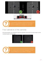
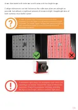
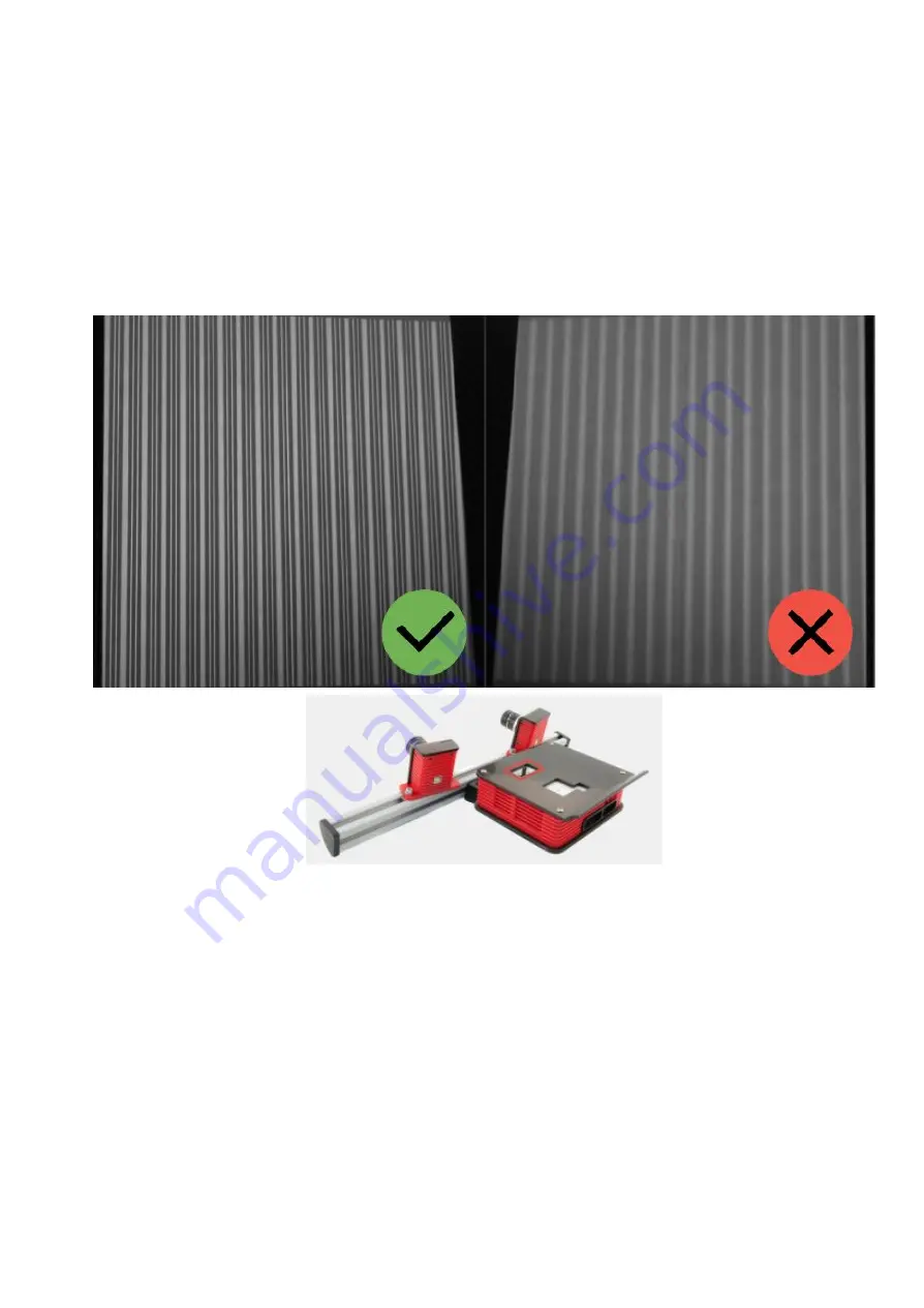
By switching the mode "Lines and Stripes", adjust the focus of the projector, so that the 
lines on the calibration plate were as sharp as possible. Check and if it’s necessary to 
adjust the projector focus. 


Bringing the cameras together 

For the work of the scanner it is necessary to point both cameras to the same position 
on the specified working distance. Install the calibration plate in front of the scanner on 
the found working distance (if you changed its position after the projector focusing 
procedure). 

Turn​


on​


the​


Cross​


light​


mode​


and​


aim​

 ​

the​


scanner​


to​


the​


calibration​


plate.​


It​


is​


not


necessary​


to​


combine​


cross​


with​


marks​


on​

 ​

the​


plate​


at​


this​


stage,​


the​


focused​

 ​

projector


should​


be​


projecting​


a​


cross​

 ​

on​


any​


surface,​


located​


at​


the​


working​

 ​

distance​


from​


the


scanner.​


Move​

 ​

the​

 ​

cameras​

 ​

on​


the​

 ​

bar​

 ​

so​

 ​

that​

 ​

the​

 ​

vertical​

 ​

line​

 ​

of​

 ​

the​


light​

 ​

cross​

 ​

lies


approximately​

 ​

on​

 ​

the​


central​

 ​

vertical​

 ​

blue​


line​


in​


the​


both​


camera​


views. 

16 

Summary of Contents for SPECTRUM

Page 1: ...RANGEVISION Setup and calibration SPECTRUM...

Page 2: ...Scanner setup ScanCenter NG launch 11 Select scanning zone 12 Calibration field parameters 13 Placing the calibration plate 13 Initial setup of cameras and lenses 14 Checking camera arrangement 15 Fin...

Page 3: ...procedures for preparing the scanner installing the required drivers calibration procedure scanning procedure and tips for acquiring high quality three dimensional object model Information may be ame...

Page 4: ...th HDMI output RAM Not less than 8 GB 3 USB ports 4 Scanning zone L M S Scanning Area WxHxD mm 520 400 400 320 250 220 120 90 100 3D point accuracy 0 12 mm 0 06 mm 0 04 mm Model Spectrum Resolution of...

Page 5: ...s R ngeVisi n 3D scanner is supplied in a protected road hard case Camera tripod is placed in a separate bag The scanner is equipped with three scanning areas Scanning area is a calibration plate and...

Page 6: ...le kit for connection to a PC 2 USB HDMI 1 2 Machine vision camera 2 3 Tripod 1 4 Calibration plate 3 5 Kit of optics 1 6 Stand for the calibration plate 2 7 USB disk with the software 1 8 License don...

Page 7: ...esired language type and path for installation After the files have been copied install drivers and graphics libraries necessary for the correct operation of RangeVision 3D scanner If you have access...

Page 8: ...Connecting projector Turn on the projector and connect it to the HDMI port of your video card After connecting the projector it should be displayed in the system If the computer has several video outp...

Page 9: ...oblems during the scanner operation you must turn off the screensaver and sleep mode By clicking right mouse button on the desktop select Personalize Screensaver and turn off the screensaver disable t...

Page 10: ...scanning module 2 Install the scanning module on tripod 3 Connect the projector with HDMI cable 4 Connect cameras with USB cables 5 Connect power supply and turn on the projector old color variant wi...

Page 11: ...ponents of the scanner are connected correctly and the connection error persists manually select hardware in Hardware settings If necessary contact the technical support of your reseller If the scanne...

Page 12: ...ructions for each step Before beginning the configuration select the desired scan area zone depending on the object scanned Scanning area is a set of interchangeable optics calibration plate and stand...

Page 13: ...the reverse side of the calibration plate Enter these values into the Configuration Wizard or select from the drop down list of previously entered values Placing the calibration plate To find a worki...

Page 14: ...oo dark Lens adjustment is carried out by rotating the ring on the objective Loosen do not unscrew the retention screw and rotate the ring Lens adjustment is carried out by the following elements 1 Th...

Page 15: ...ocated in Settings Software Cameras menu Finding a working distance The scanner has own working distance distance to the object for each scanning area When you configure your scanner this distance is...

Page 16: ...work of the scanner it is necessary to point both cameras to the same position on the specified working distance Install the calibration plate in front of the scanner on the found working distance if...

Page 17: ...Final calibration of the cameras After the cameras are positioned align the projected cross with the central mark on the calibration plate and proceed 17...

Page 18: ...ch as possible without getting overexposure 4 Adjust the lens sharpness It is convenient to use camera view zoom by left clicking the camera views to assess sharpness Set the projector to the lines an...

Page 19: ...overlit areas with too bright image Configure lenses iris so that the lines on the calibration plate are as bright as possible but without a significant amount of excessive light Image brightness of b...

Page 20: ...f the stripes Visually lines and stripes must be the same brightness Upon completion of all scanner adjustments you should fulfil the following conditions cameras are pointed to one point located at t...

Page 21: ...the scanning area if you suspect that scanning accuracy got worse after transporting the scanning complex Orientation is used if you suspect that the camera moved due to unreliable mounting if you wa...

Page 22: ...for Spectrum L is the largest and S is the smallest The approximate size of plates is specified in the Scanner setup section For calibration of rotary table on the S scan area you should use the axis...

Page 23: ...Calibration procedure 1 In the dropdown list the previously selected in onfiguration wizard calibration plate size is chosen Compare it to the actual calibration field choose it from the list if neede...

Page 24: ...ameras matches the markers on the plate the cross is projected on the central marker 3 If the plate placement is incorrect a error message will appear Correct the placement and repeat the step In case...

Page 25: ...tance from the center of the plate to the scanner when turning the plate The exception are only snapshots in positions 10 and 11 do not rotate the plate at a very high angle Ensure that all marks on t...

Page 26: ...ng the steps make two more shots after this the accuracy of orientation will be shown It should be approximately equal to the accuracy value of the last calibration If the accuracy during orienting st...

Page 27: ...the calibration field in focus The focus assessment option can help with this task It is located in the Hardware settings Cameras menu When activated the software will monitor the calibration snaps an...

Page 28: ...wn to the right is in compliance with Waste Electrical and Electronic Equipment Directive 2002 96 EC WEEE The mark indicates the requirement NOT to dispose the equipment as unsorted municipal waste bu...

Reviews: