background image

INSTALLATION 

Check the appliance is electrically safe and gas sound when you have finished.

25

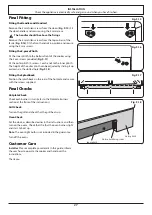
Flexible hose

Pipework

Pipework

Flexible hose

Conversion to Another Gas

If the appliance is to be converted to another gas do the 

conversion at this point. See the conversion section of these 

instructions.

Levelling

You are recommended to use a spirit level on a shelf in one of 

the ovens to check for level.
Place the cooker in its intended position taking care not to 

twist it within the gap between the kitchen units as damage 

may occur to the cooker or the units.
The front feet and rear rollers can be adjusted to level the 

cooker. 
To adjust the height of the rear of the cooker use the levelling 

tool supplied to turn the adjusting nuts at the front bottom 

corners of the cooker. To set the front turn the feet bases to 

raise or lower.

Gas Connection

This must be in accordance with the relevant standards.
The flexible hose (not supplied with the cooker) must be 

in accordance with the relevant standards. Hoses may be 

purchased at most builders’ merchants.
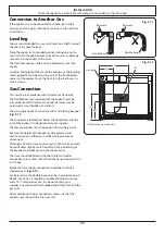
The gas supply needs to terminate with a side facing bayonet 

(

Fig. 9.11

). 

The connector is located just below the hotplate level at the 

rear of the cooker. If in doubt contact your supplier.
The rear cover boxes limit the position of the supply point.
Because the height of the cooker can be adjusted and 

each connection is different, it is difficult to give precise 

dimensions.
Although a 900 mm hose can be used, a 1250 mm (maximum) 

hose will allow slightly more flexibility in the positioning of 

the bayonet and make moving the cooker easier.
The hose should be fitted so that both inlet and outlet 

connections are vertical so that the hose hangs downwards in 

a ‘U’ shape. 
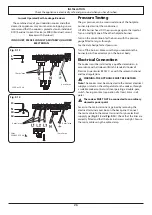
Ideally the hose supply connection should be within the 

shaded area ‘A’ (

Fig. 9.12

).

For Natural Gas, the flexible hose must be in accordance with 

BS 669. For LP Gas, it should be capable of 50 mbar pressure 

and a 70 °C temperature rise. If in doubt contact, your 

supplier. Screw connect the threaded end of the hose into the 

gas inlet.
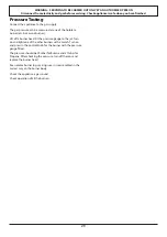
After completing the gas connection, make sure that the 

cooker is gas sound with a pressure test.

470

350

675

A

315

All dimensions in millimetres

Gas inlet

Fig. 9.11 

Fig. 9.12 

Summary of Contents for Classic 90 Dual Fuel - 3 Button Clock

Page 1: ...Classic 90 Dual Fuel 3 Button Clock Built from experience U110719 01A USER GUIDE INSTALLATION INSTRUCTIONS...

Page 2: ...ook Twitter message or Instagram comment 4 We cannot guarantee your kitchen will be professionally photographed 4 Any photographs received and professional photographs taken will belong to AGA Rangema...

Page 3: ...le 16 Glide out Grill 16 Control Panel and Doors 16 Ovens 17 Cleaning table 18 7 Troubleshooting 19 8 Installation 21 Dear Installer 21 Safety Requirements and Regulations 21 Provision of Ventilation...

Page 4: ...ii...

Page 5: ...children away from the cooker and never wear loose fitting or hanging clothes when using the appliance DO NOT use a steam cleaner on your cooker Always keep combustible materials e g curtains and flam...

Page 6: ...off at the mains before cleaning or carrying out any maintenance work DO NOT use the control knobs to manoeuvre the cooker NEVER operate the cooker with wet hands DO NOT use a towel or other bulky cl...

Page 7: ...rse The inside door face is constructed with toughened safety glass Take care NOT to scratch the surface when cleaning the glass panel Accidental damage may cause the door glass panel to fracture Keep...

Page 8: ...el wool oven cleaning pads or any other materials that will scratch the surface NEVER store flammable materials in the drawer This includes paper plastic and cloth items such as cookbooks plastic ware...

Page 9: ...t When the igniter button is pressed in sparks will be made at every burner this is normal Do not attempt to disassemble or clean around any burner while another burner is on otherwise an electric sho...

Page 10: ...estos or mesh mats are NOT recommended Fig 2 6 They will reduce burner performance and could damage the pan supports You should also avoid using unstable and misshapen pans that may tilt easily and pa...

Page 11: ...stick and metal cooking utensils e g spatulas will damage the surface Use heat resistant plastic or wooden utensils n n Do not put it crossways it will not fit properly and will be unstable Fig 2 12 n...

Page 12: ...sults slide the carriage back into the grill chamber and preheat the appropriate part s of the grill for two minutes The grill trivet can be removed and the food placed on it while you are waiting for...

Page 13: ...an ovens circulate hot air continuously which means faster more even cooking The recommended cooking temperatures for a fan oven are generally lower than those for a non fan oven Note Please remember...

Page 14: ...upplied with four flat cooking shelves Fig 3 5 and a plate warming shelf Fig 3 6 When using the tall oven you can cook on all four shelves at the same time but make sure that they are well spaced out...

Page 15: ...ress the mode M button once Fig 4 2 The bell symbol will flash on the display Select the desired countdown from 00 01h to 23 59h using the button Fig 4 3 The countdown will automatically begin and the...

Page 16: ...rent time will be displayed along with the word AUTO Fig 4 9 3 Set the oven to the required cooking temperature 4 During the cook period the cook symbol is illuminated in the display 5 When cooking is...

Page 17: ...es Other containers should be placed centrally Keep all trays and containers away from the back of the oven as overbrowning of the food may occur For even browning the maximum recommended size of a ba...

Page 18: ...es 10 20 minutes according to size 20 40 minutes according to size 2 3 hours 45 60 minutes 40 45 minutes 2 to 3 hours 20 30 minutes 15 20 minutes 15 20 minutes per 500g Steaks according to thickness C...

Page 19: ...urner heads and caps can be removed for cleaning n n DO NOT put the burner heads in a dishwasher Make sure they are absolutely dry before replacing them The Single Ring Burners When refitting the burn...

Page 20: ...support frame by pulling the grill pan forward Lift the grill pan clear of the support frame The support frame is held to the side rails by two clips on each side Fig 7 5 For each side support the sid...

Page 21: ...p all marks on the lining but helps to reduce the amount of manual cleaning needed The Cook Clean panels work better above 200 C If you do most of your cooking below this temperature occasionally remo...

Page 22: ...oth supermarket Sides and plinth Painted surface Hot soapy water soft cloth Splashback rear grille Enamel or stainless steel Hot soapy water soft cloth Cream cleaner with care if necessary Control pan...

Page 23: ...lectrical supply remember to reset the clock to make sure that the timed oven continues to operate Food is cooking too slowly too quickly or burning Cooking times may differ from your previous oven Ch...

Page 24: ...3 Loosen the bottom hinge fixing screws and use the notch and a flat bladed screwdriver to move the position of the hinge to set the hinge position Fig 8 4 Retighten the hinge screws NOTE The tall ov...

Page 25: ...r other non permanent dwelling or BS5482 3 when the installation is in a boat The Gas Safety Installation and Use regulations The relevant Building IET regulations In the Republic of Ireland the cooke...

Page 26: ...ed in a room or internal space below ground level e g in a basement You will need the following equipment to complete the cooker installation satisfactorily Stability bracket If the cooker is to be su...

Page 27: ...d rear of the appliance should be heat splash and steam resistant Certain types of vinyl or laminate kitchen furniture are particularly prone to heat damage and discolouration We cannot accept respons...

Page 28: ...hain should be kept as short as is practicable and fixed firmly to the rear of the cooker If you are using a stability bracket first attach the bracket location device to the rear of the cooker Fig 9...

Page 29: ...ses may be purchased at most builders merchants The gas supply needs to terminate with a side facing bayonet Fig 9 11 The connector is located just below the hotplate level at the rear of the cooker I...

Page 30: ...tated on the voltage label on the cooker through a suitable cooker control unit incorporating a double pole switch having a contact separation of at least 3mm in all poles n n The cooker MUST NOT be c...

Page 31: ...1 each end to the inner plinth The height of the outer plinth can be adjusted by sliding it up or down via the slotted hole Fig 9 18 Fitting the Splashback Position the splashback on the rear of the h...

Page 32: ...or unauthorised gas controls n n Disconnect from the electricity supply before servicing n n Before electrical reconnection check that the appliance is electrically safe Injectors Remove the burner ca...

Page 33: ...k burner Lift off a burner head Fit the pressure gauge to the jet Turn on and light one of the other burners with a match Turn on and press in the control knob for the burner with the pressure gauge f...

Page 34: ...se The ratings are for 230V 50Hz Code Colour b Blue br Brown bk Black or Orange r Red v Violet w White y Yellow g y Green yellow gr Grey Code Description A1 Grill front switch A2 Grill energy control...

Page 35: ...atural Gas 20 mb L P Gas Injector Injector Wok burner 57 4kW internal 78 3 54 kW 285 g h internal 53 external 126 external 82 Rapide Large Burner 40 3 kW 134 3 0 kW 210 g h 87 Semi Rapide Medium Burne...

Page 36: ...rners 5 Auxiliary Small Burner EE gas burner Semi Rapide Medium Burner EE gas burner 58 Semi Rapide Medium Burner EE gas burner 58 Rapide Large Burner EE gas burner 56 Rapide Large Burner EE gas burne...

Page 37: ...ency Fuel type Electric Cavity type Fanned Power conventional kW Power forced air convection kW 2 5 Volume Litres 67 Energy consumption electricity conventional kWh cycle Energy consumption electricit...

Page 38: ...34 Notes...
Page 39: ...d by persons or organisations other than those authorised to act on behalf of AGA Rangemaster Exceptions Items not included under the free 1 year guarantee include pan supports griddles wok rings baki...

Page 40: ...f any particular appliance Clarence Street Royal Leamington Spa Warwickshire CV31 2AD England Consumer Services 44 0 1926 457628 Fax 44 0 1926 450526 E mail consumers agarangemaster co uk www rangemas...

Reviews: