background image


Range Road Enterprises Ltd


Box 944


Eckville AB T0M 0X0


www.range-road.ca


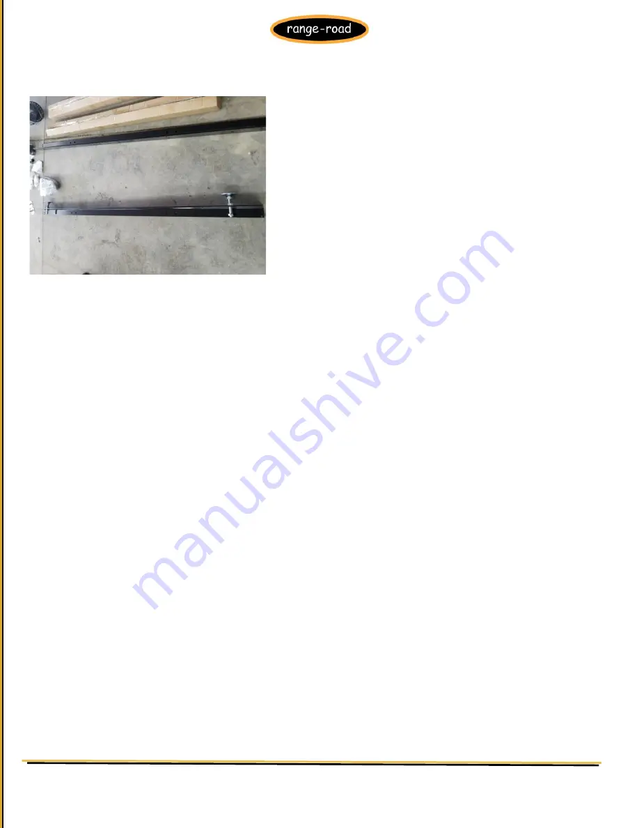
3)  Place 2 guide rails on the floor and install 2 or 3 levelling feet in the large round holes on the bottom of each rail 


4)  Place the 2 rails on their levelling feet parallel to each other, 

the measurement from center to center will be roughly:


RR5022 & RR5026  845mm (33 3/8

”) 

RR5029                    902mm 

(35 ½”) 

RR5032                    

1008mm (39 11/16”) 

RR5036A                 1099mm (43 ¼”) 

Alternatively: assemble track without setting width, then: 

1)  You can assemble the sawmill head assembly, them measure the distance between the left and 

right rollers on the sawmill head, that will give you the width that you need for setting the track 
width. OR 

2)  You can assemble the sawmill head assembly, and loosely assemble the track, then set your 

assembled head onto the loose track, the track will automatically move out to the proper width, 
then run the sawmill head slowly down and up the track to set the width along the entire length of 
the track. 

Any of the above procedures will be suitable for setting the track width. 


For any Sawmill to cut square and straight all pieces have to be squared to each other 
and level. Use the adjusting feet to level one rail and then make sure the second rail is 
level with the first one. 


Summary of Contents for RR5029

Page 1: ...ca Range Road RR5022 RR5026 RR5029 RR5032 Saw Mill Owner s Manual WARNING Read carefully and understand all ASSEMBLY AND OPERATION INSTRUCTIONS before operating Failure to follow the safety rules and...

Page 2: ...ng length of 125 TECHNICAL SPECIFICATIONS Model RR5022A B RR5026A RR5029B RR5032A B Capacity 51cm 22 diameter 17 5cm 7 thick 315cm 124 in length 66cm 26 diameter 16 5cm 6 thick 315cm 124 length 74cm 2...

Page 3: ...ask if working in dusty work conditions This applies to all persons in the work area Also use non skid safety shoes hardhat gloves dust collection systems and hearing protection when appropriate SAW M...

Page 4: ...hers nearby 3 Operation of this equipment may create sparks that can start fires around brush and dry vegetation A spark arrestor may be required The operator should contact local fire agencies for la...

Page 5: ...ssories etc in accordance with these instructions and in the manner intended for the particular type of equipment taking into account the working conditions and the work to be performed Use of the equ...

Page 6: ...ces of ignition around the equipment especially when refueling o Do not refill the fuel tank while the engine is running or hot o Do not fill fuel tank to the top Leave a little room for the fuel to e...

Page 7: ...assembling it please have a qualified technician assemble it Note For any additional information regarding the saw mill parts refer to Assembly Diagram near the end of this manual 1 Open the package a...

Page 8: ...e the distance between the left and right rollers on the sawmill head that will give you the width that you need for setting the track width OR 2 You can assemble the sawmill head assembly and loosely...

Page 9: ...5 Place the log support cross tubes on each end and put the bolts in snugly but do not tighten The log support cross tube that the next rails will also attach to has 4 holes on each side this rail wi...

Page 10: ...www range road ca 6 Check your width measurement again RR5022 RR5026 845mm 33 RR5029 902mm 35 RR5032 1008mm 39 11 16 7 Do cross measurements now to make sure the rails are square to each other RR5022...

Page 11: ...t cross tubes and recheck levelness and squareness adjust as needed 9 Mount and tighten centre log support cross tube 10 Put the levelling feet on next 2 rails and put them in position at the centre l...

Page 12: ...rect distance apart at both ends and put on the end log support cross tube do not tighten the bolts 14 Cross measure new rails and adjust 15 When rails are square and level tighten 8 bolts in log supp...

Page 13: ...iew 2 25 with the pulleys on them and place them into the head unit square tubes remove the bolts and pulleys pay attention to where the pulley spacers go place these to the side 17 Cut the cardboard...

Page 14: ...terprises Ltd Box 944 Eckville AB T0M 0X0 www range road ca 19 Loosen the 4 corner bolts on the top frame 20 Place the top frame upside down and put the 2 galvanized corner posts in and tighten all 4...

Page 15: ...ww range road ca 21 Tighten all 4 corner bolts to hold posts in place 22 Lift and rotate the top frame so it is right side up and position it at head unit 23 Put the back cover in position and put bot...

Page 16: ...944 Eckville AB T0M 0X0 www range road ca 24 Put the back cover on the water tank side and put the bolts in 25 Place spacers and pulleys on bottom bolts pulley circlips face the spacers put nuts and w...

Page 17: ...d Enterprises Ltd Box 944 Eckville AB T0M 0X0 www range road ca 26 Lift complete head unit out of crate 27 Mount left and right roller assemblies onto the galvanized tubes snug bolts up but do not tig...

Page 18: ...ises Ltd Box 944 Eckville AB T0M 0X0 www range road ca 28 Position head unit over track and line rollers up so that the track sits in the roller groove set head unit onto tracks 29 Tighten all 8 bolts...

Page 19: ...stall roller stops at all 4 frame corners 31 Mount control handle at preferred working height on right hand post making sure throttle cable is not twisted tighten all 4 bolts Take note that 32A 36A mo...

Page 20: ...r sits behind the bar at base where 2 bolts secure it 33 Tighten bolt in water tank mount bracket and put water tank in the copper end on the water tank hose runs through the hole in the frame above t...

Page 21: ...r tank The fuel tank frame bolts to the top of the sawmill with 4 bolts the fuel tank itself does not bolt to the frame it sits on the mount using the weight of the fuel to hold it in The rubber gromm...

Page 22: ...es gently lower the head unit so it sits unsupported on the posts For 22A B 26A 32A B models 37 Wind the lift handle so that the pulley arms are all the way in then find the two stubs on the inside of...

Page 23: ...te the same as the smaller mills for the most part but you can easily see the 36 model has the cables joined near the winch so that only one cable actually goes down to the winch The winch can be moun...

Page 24: ...ables up Use handle OR winch to lift the head unit 152mm 205mm 6 8 and place a level on the top of blade cover adjust cables until head is level Measure distance from the blade log support on each sid...

Page 25: ...Box 944 Eckville AB T0M 0X0 www range road ca 40 Install T handles into track cross supports to hold the log supports in place adjust bracket on head unit so that the blade is protected if the head is...

Page 26: ...lowing instructions BEFORE any adjustment loosen Bolts 96A and 96B and Nuts 98A and 98B If after replacement Blade starts to shift back towards operator loosen Nut 98C and hold Bolt 99 with a wrench T...

Page 27: ...tment For horizontal Blade adjustment loosen the Nut 15 see Assembly Diagram and adjust the left and right Cable Anchor Bolts 159 until the distance between the ends of the Blade and the top of the Mi...

Page 28: ...for damaged loose or missing parts before operating If any problems are found do not use equipment until fixed properly Start Procedure Before starting the engine A Follow the Set Up Instructions to p...

Page 29: ...cut logs containing foreign objects nails metal etc This will cause Blade damage and could cause serious injury 7 Choose the Short Log Supports 9 or the Long Log Supports 10 according to the log diame...

Page 30: ...ale Pointer points to the desired thickness Tighten both T Handles 18 13 The cut direction must be as shown below If the log is cut from the other direction the saw blade will push the log away from t...

Page 31: ...and wait for the engine to cool before performing any inspection maintenance or cleaning procedures TO PREVENT SERIOUS INJURY FROM EQUIPMENT FAILURE Do not use damaged equipment If abnormal noise vib...

Page 32: ...bjects in the logs 1 Use recommended blade only 2 Use lower speed 3 Reduce speed increase feed pressure 4 Properly install blade 5 Tension blade properly 6 Remove metal or object Blade cuts crooked 1...

Page 33: ...Range Road Enterprises Ltd Box 944 Eckville AB T0M 0X0 www range road ca Parts List...

Page 34: ...Range Road Enterprises Ltd Box 944 Eckville AB T0M 0X0 www range road ca...

Page 35: ...Range Road Enterprises Ltd Box 944 Eckville AB T0M 0X0 www range road ca...

Page 36: ...Range Road Enterprises Ltd Box 944 Eckville AB T0M 0X0 www range road ca...

Page 37: ...Range Road Enterprises Ltd Box 944 Eckville AB T0M 0X0 www range road ca...

Page 38: ...any parts of the product In fact the Manufacturer and or Distributor expressly states that all repairs and parts replacements should be undertaken by certified and licensed technicians and not by the...

Reviews: