background image

24

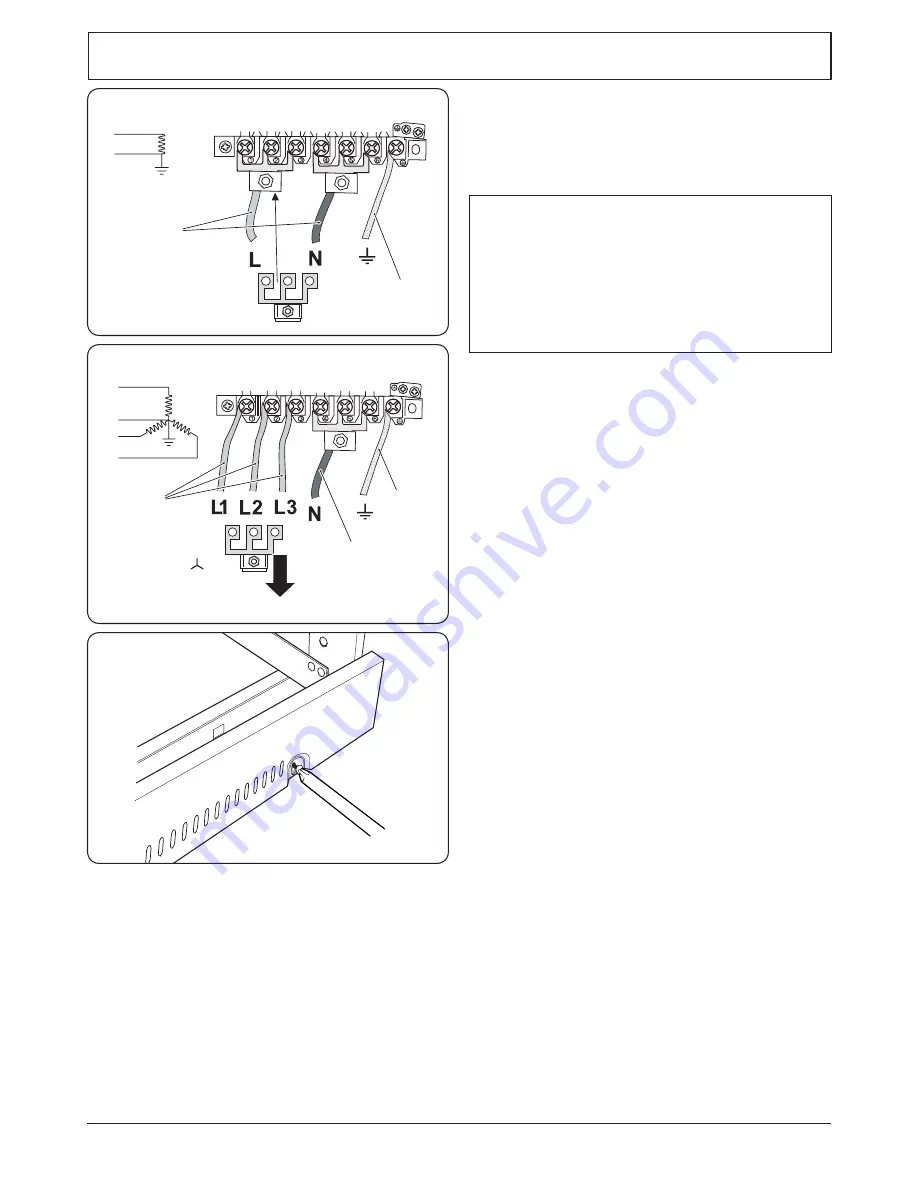
ArtNo.130-0010 Electrical connections single-phase

L

N

230 V ac 50 Hz

10 mm² max

6 mm² max

Electrical Connection

The cooker must be installed by a qualified electrician, in 

accordance with all relevant British Standards/Codes of 

Practice (in particular BS 7671), or with the relevant national 

and local regulations.

Current Operated Earth Leakage Breakers

The combined use of your cooker and other domestic 

appliances may cause nuisance tripping, so we 

recommend that the cooker is protected on an individual 

RCD (Residual Current Device) or RCBO (Residual Current 

Breaker with Overload).

IF IN DOUBT, PLEASE CONSULT A SUITABLY QUALIFIED 

ELECTRICIAN.

Note: 

The cooker must be connected to the correct electrical 

supply as stated on the voltage label on the cooker, through 

a suitable cooker control unit incorporating a double-pole 

switch, having a contact separation of at least 3 mm in all 

poles.

n

n

The cooker MUST NOT be connected to an ordinary 

domestic power point.

Access to the mains terminal is gained by removing the 

electrical terminal cover box on the back panel. Connect 

the mains cable to the correct terminals for your electrical 

supply type (

Fig.7.15

 and 

Fig.7.16

). Check that the links are 

correctly fitted and that the terminal screws are tight. Secure 

the mains cable using the cable clamp.

Final Checks

Hotplate Check

Check each burner in turn (refer to the 

‘Hotplate Burners’


section at the front of the instructions).

Grill Check

Turn on the grill control and check that the grill heats up.

Oven Check

Set the clock as described earlier in the instructions, and then 

turn on the ovens. Check that the oven fans start to turn and 

that the ovens start to heat up.

Note:

 The oven light bulb is not included in the guarantee.

Turn off the oven.

Fitting the Plinth

Loosen the 3 screws along the front bottom edge of the 

cooker. Hook the central keyhole over the central screw. Twist 

and fit each end keyhole over their respective screws.Tighten 

the fixing screws 

(Fig.7.17)

.

Customer Care

Installer:

 Please complete your details in this guide, inform 

the user how to operate the cooker and hand over the 

instructions.

Thank you.

ArtNo.350-0012 - Securing the plinth

L1

N

L3
L2

3N ac

230/400 V 50 Hz

6 mm² max

10 mm² max

6 mm² max

INSTALLATION

Check the appliance is electrically safe and gas sound when you have finished.

Fig.7.15 

Fig.7.16 

Fig.7.17 

Summary of Contents for Classic 110

Page 1: ...Classic 110 Dual Fuel Lidded Rangemaster 110 Dual Fuel Lidded Toledo 110 Dual Fuel Lidded Britain s No 1 Range Cooker USER GUIDE INSTALLATION INSTRUCTIONS...

Page 2: ...sugar and serve immediately with cream or cr me fraiche FRUITY BAKED PUDDING Serves 4 6 Ingredients 3kg 6 lb skinned and boned loin of pork 2 x 70g packs prosciutto Grated zest of 2 lemons Bay leaves...

Page 3: ...Burners 13 The Griddle 13 Grill 14 Control Panel Doors and Glass Lid 14 Ovens 14 6 Troubleshooting 16 7 Installation 18 Dear Installer 18 Safety Requirements and Regulations 18 Provision of Ventilatio...

Page 4: ...iv...

Page 5: ...an hour Before using the grill for the first time you should also turn on the grill and run for 30 minutes with the grill pan in position pushed fully back and the grill door open Make sure the room i...

Page 6: ...eyond the smoking point n n WARNING Unattended cooking on a hob with fat or oil can be dangerous and may result in fire n n NEVER leave a chip pan unattended Always heat fat slowly and watch as it hea...

Page 7: ...g on them should be placed level with the front edge of the oven s wire shelves Other containers should be placed centrally Keep all trays and containers away from the back of the oven as overbrowning...

Page 8: ...t at the front Fig 2 2 The glass lid has a safety device which cuts off the hotplate burner gas supply if the lid is accidentally closed with a burner on DO NOT use this to turn the burners off The ga...

Page 9: ...e that the flames are under the pans Using a lid will help the contents boil more quickly Fig 2 5 Large pans should be spaced well apart Pans and kettles with concave bases or down turned base rims sh...

Page 10: ...t front to back Fig 2 12 It is designed for cooking food on directly DO NOT use pans of any kind on it The griddle surface is non stick and metal cooking utensils e g spatulas will damage the surface...

Page 11: ...control will come on For best results slide the grill pan back into the grill chamber and preheat the appropriate part s of the grill for two minutes The grill trivet can be removed and the food plac...

Page 12: ...o quickly so we recommend that the food be positioned in the lower half of the oven to cook The oven temperature may also need to be lowered Similar items being cooked will need to be swapped around f...

Page 13: ...ok for The stop time which is the time of day you want the oven to stop cooking To Stop the Ovens Automatically Press and hold the Stop Time button Fig 2 26 and then press the button or button until t...

Page 14: ...key symbol and OF will now show on the display Fig 2 33 Release the buttons The ovens are now locked as confirmed by the display showing the time of day alongside the key symbol Fig 2 34 To turn off t...

Page 15: ...two different heights One of the oven shelves must be removed and the other positioned to suit When the Handyrack is used in its highest position other dishes can be cooked on the bottom shelf positio...

Page 16: ...0 minutes according to size 2 3 hours 45 60 minutes 40 45 minutes 2 to 3 hours 20 30 minutes 15 20 minutes 15 20 minutes per 500g Steaks according to thickness Conventional Oven Temperature C Shelf Po...

Page 17: ...e that the notch lines up with the electrode or hole in the base Check that the burner head is level and that the cap is fitted centrally on the burner head Fig 5 1 The Wok Burner When reassembling th...

Page 18: ...he sides see the Moving the Cooker section under Installation Open the oven door slightly and remove the front panel fixing screws from the door sides two each side Fig 5 5 Carefully lift off the oute...

Page 19: ...ll purpose cloth supermarket Sides and plinth Painted surface Hot soapy water soft cloth Splashback rear grille Enamel or stainless steel Hot soapy water soft cloth Cream cleaner with care if necessar...

Page 20: ...nstaller Power failure In the event of a failure in the electrical supply remember to reset the clock to make sure that the timed oven continues to operate Food is cooking too slowly too quickly or bu...

Page 21: ...ing care to protect your fingers with a glove in case the bulb should shatter unscrew the old bulb Screw in the new bulb screw back the bulb cover Turn on the circuit breaker and check that the bulb n...

Page 22: ...ion and Use regulations The relevant Building IEE regulations In the Republic of Ireland The installation must be carried out by a competent person and installed in accordance with the current edition...

Page 23: ...ctorily Stability bracket If the cooker is to be supplied with gas through a flexible hose a stability bracket or chain MUST be fitted These are not supplied with the cooker but are available at most...

Page 24: ...hob Surfaces of furniture and walls at the sides and rear of the appliance should be heat splash and steam resistant Certain types of vinyl or laminate kitchen furniture are particularly prone to heat...

Page 25: ...bottom of the fascia panel as you move the oven Fig 7 7 Carefully push the cooker backwards off the base tray Remove the base tray Position the cooker close to its final position leaving just enough...

Page 26: ...elf in one of the ovens to check for level Place the cooker in its intended position taking care not to twist it within the gap between the kitchen units as damage may occur to the cooker or the units...

Page 27: ...utlet connections are vertical so that the hose hangs downwards in a U shape Ideally the hose supply connection should be within the shaded area A Fig 7 14 For Natural Gas the flexible hose must be in...

Page 28: ...Connect the mains cable to the correct terminals for your electrical supply type Fig 7 15 and Fig 7 16 Check that the links are correctly fitted and that the terminal screws are tight Secure the mains...

Page 29: ...uthorised gas controls n n Disconnect from the electricity and gas supply before servicing n n Before electrical reconnection check that the appliance is electrically safe Injectors Remove the burner...

Page 30: ...as sound The gas pressure can be measured at one of the hotplate injectors not the wok burner Lift off a burner head Fit the pressure gauge to the jet Turn on and light one of the other burners Turn o...

Page 31: ...ven control B3 Left hand oven base element B4 Left hand oven top element B5 Left hand oven browning element C Clock D1 Right hand fan oven thermostat D2 Right hand fan oven switch D3 Right hand fan ov...

Page 32: ...8 3 5kW 246g h internal 53 external 126 external 82 Large burner 40 3 0kW 134 3 0kW 210 g h 87 Medium burner 32 1 7kW 109 1 7kW 119 g h 68 Small burner 28 1 0kW 75 1 0kW 70 g h 51 The valves in this c...

Page 33: ...29 Notes...

Page 34: ...30 Notes...

Page 35: ...authorised to act on behalf of AGA Rangemaster Exceptions Items not included under the free 1 year warranty include pan supports griddles wok rings baking trays grill pans trivets filters light bulbs...

Page 36: ...ed Office Juno Drive Leamington Spa Warwickshire CV31 3RG Search Rangemaster UK Rangemaster continuously seeks improvements in specification design and production of products and thus alterations take...

Reviews: