background image

Manual-6

Test the Via 10’s RS-232 port (optional) by running

Windows’ HyperTerminal program found under 

Start >

Programs > Accessories > HyperTerminal

. With

HyperTerminal running and the Via 10’s RS-232 port hooked
up to the computer’s RS-232 port using (unfortunately) a null
modem cable, click the 

Test 232

 button on the Via 10

Configuration screen. If working properly, the message: “

232

Test

” shows in the HyperTerminal screen. This verifies that

the baud and parity settings are correct.

Note: A null modem cable is required for this test because

the Via 10’s RS-232 port must “look like” a terminal to the
computer.

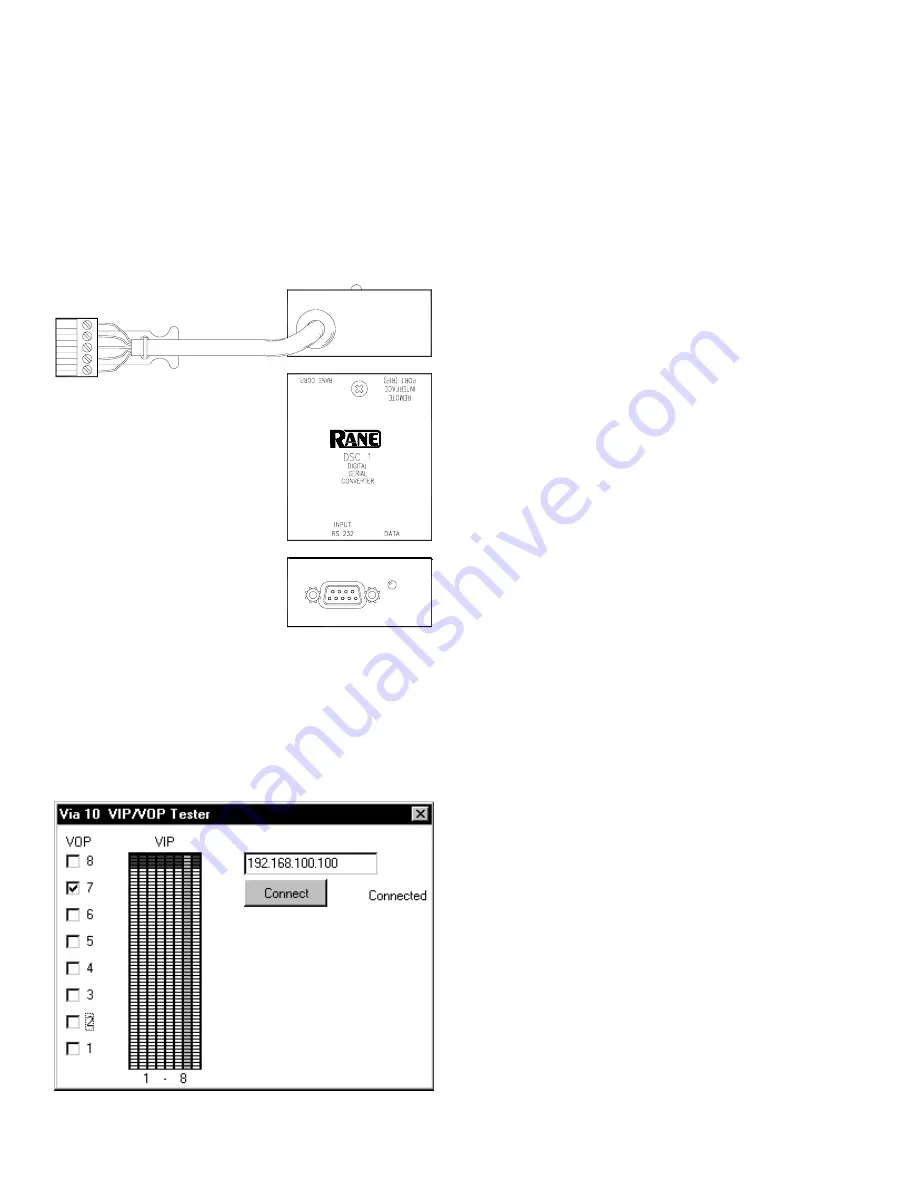
Test the VIP & VOP ports (optional) by looping them

together so data sent out of the VOP appears on the VIP.
Connect VOP 1 to VIP 1, VOP 2 to VIP 2, etc. Then run the

VIPVOP

 utility. The default location after installation is:

C:\Program Files\Rane Corporation\VIPVOP

. In the box in

the upper right corner of the 

VIPVOP

 screen, type in the

proper IP address of the Via 10 you are testing. Then click the

Connect 

button; the green LED on the 

VIPVOP

 screen lights

when connection is successful.

VIPVOP

 displays 8 VOP check boxes down the left side;

when checked, the corresponding Via 10 VOP pin is pulled
low (0 volts/ground). When unchecked, the corresponding
VOP pin is pulled high (+5 VDC).  Since the VOP pins were
previously connected directly to the corresponding VIP pins,
any changes to the VOP check boxes should immediately
show up on the VIP meters in the center of the 

VIPVOP

screen. VIP pin 1 is the left-most meter, then pin 2, 3, et
cetera, with VIP pin 8 on the far right. Connect a potentiom-
eter to the VIP to vary the voltage and display the correspond-
ing meter reading on the vipvop screen.

Hardware

This section discusses each of the Via 10 hardware ports.

As the title suggests, here you’ll find the hardware details for
each. Software details as well as applications are found in –
you guessed it – the Software and Applications section on
page Manual-8.

Hardware 1: RS-232 & the RW 232

RS-232 with Rane RW 232. The RS-232 port on the Via

10 can be hooked directly to the RW 232 Input port on any
Rane RW 232 device allowing extended communication
distances up to 305 feet (100 meters) over a standard 10Base-
T Ethernet LAN. ActiveX controls for commonly controlled
parameters on the following Rane products are accessible
using any ActiveX capable software development tool: RPE
228d, RPM 26v, ECB 62, ECM 64, RPD 1. (See Applications
Using ActiveX
  on page Manual-10 for software and control
details for these products.) In English what this means is that
through a little bit of software know-how, one can, for
example, draw a slider on a web page, then link the slider’s
operation to the Master Output Level control on the Rane
RPM 26v. But, since this is the Hardware section of the
Manual, we’re a bit premature in even mentioning software
here.

The default settings of the Via 10’s RS-232 port support

RW 232 communications. If RW 232 devices are being used
with the Via 10 RS-232 port, the shipped baud and parity
settings of the RS-232 port need not be changed. Just in case,
the default settings are listed below. Only 8-bit wide words
are supported—no 7-bit words.

Via 10 Default RS-232 Communications Settings

(required for RW 232 use)

Baud

Parity Start bit

Stop bit

RS-232 cable length

19200 Even

1 (always) 1 (always) 50 feet max

VIPVOP screen

Testing the Via 10’s RS-485

port (optional) takes one extra
piece of hardware. The Rane DSC 1
accessory is an RS-485 to RS-232
converter that is useful for this test.
Run Windows’ HyperTerminal
program found under ‘

Start >

Programs > Accessories >
HyperTerminal

.’ With

HyperTerminal running and the Via
10’s RS-485 port hooked up
through an RS-485 (or RS-422) to
RS-232 converter using a null
modem cable hooked to the computer’s RS-232 port, hit the

Test 485

 button on the Via 10 Configuration screen. If

working properly, the message: ‘

485 Test

’ shows in the

HyperTerminal screen.

Note: A null modem cable is required for this test because

the Via 10’s RS-485 port must “look like” a terminal to the
computer.

Summary of Contents for Via 10

Page 1: ...d rear panel controls found on the Via 10 page Manual 2 Part two is Configuring the Via 10 PC page Manual 4 which explains what the Via 10 Config Utility does It also reviews the computer setup that is required so the computer can talk through the Via 10 s IP Internet Protocol language Part three goes over the Hardware details of the Via 10 s I O ports page Manual 6 Four sections are found RS 232 ...

Page 2: ...r illuminates when there is activity on the Via 10 s RS 232 port 햴 RS485 indicator flashes when there is activity on the Via 10 s RS 485 port 햵 CONFIG button is recessed only used to set the Via 10 s IP address during initial setup See Configuring the Via 10 PC on page Manual 4 햶 PWR indicator lights when the Via 10 is powered It flashes when in Via 10 CONFIG mode ...

Page 3: ...ble logic and or A D input port for use with external switches potentiometers or any zero to five volt instrumentation device Up to eight input devices in any variety are supported See the Hardware VIP section on page Manual 7 for further details 햷 Versatile Output Port VOP is a splendidly programmable open collector logic output port for use with external indicator lamps LEDs relays or any ground...

Page 4: ...ernet adapter NIC or Network Interface Card installed in the PC If installed its operation may be checked by right clicking on My Computer followed by a left click on the selection Properties and again a left click on the Device Man ager tab of the System Properties dialog box Click on the plus sign to the left of Network Adapters to view the configured adapters A malfunctioning adapter is indicat...

Page 5: ... web site www rane com then select Run from Windows Start menu and Browse to the floppy drive or file and double click SETUP to run the VIACONFIG install routine 2 If you power up a new Via 10 it comes up in config mode which is indicated by a flashing POWER LED If it s not already place the Via 10 in config mode by unplugging the power then hold in the Via 10 s front panel CONFIG button with a pe...

Page 6: ...and Applications section on page Manual 8 Hardware 1 RS 232 the RW 232 RS 232 with Rane RW 232 The RS 232 port on the Via 10 can be hooked directly to the RW 232 Input port on any Rane RW 232 device allowing extended communication distances up to 305 feet 100 meters over a standard 10Base T Ethernet LAN ActiveX controls for commonly controlled parameters on the following Rane products are accessib...

Page 7: ...e hair out debug ging problems Only the most distant SR 1L connected to the Via 10 should have its RT switch ON which connects a 150 ohm terminating resistor SRM 66 Use The SRM 66 contains an RS 485 port called RIP for Remote Interface Port which may be wired to the Via 10 s RS 485 port for SRM 66 control over a LAN however you cannot connect both an SRM 66 and SR 1L remote s to the same Via 10 on...

Page 8: ...e an object a piece of software code which fully describes a device while hiding the implementation details such as protocol from the pro grammer By hiding the communication details there is no longer a need for different manufacturers devices to agree on protocol This lack of a protocol standard means that coopera tion between manufacturers is not required It allows each manufacturer to choose th...

Page 9: ...ck or turning a system off at a certain time or adjusting delay time as the temperature changes Microsoft FrontPage 2000 ActiveX example Many use Microsoft s FrontPage 2000 to create user interface web pages for computer controlled systems These web pages may or may not be accessible over the Internet The examples found on Rane s web site will review the basic FrontPage 2000 procedures to link scr...

Page 10: ...rontPage C Delphi or Lab View allow programming each VIP pin independently thus providing any combina tion of up to eight applications Thus with software scripts there is an unlimited number of possibilities for the VIP Use multiple hardware switches and or logic output ports on other system devices to recall system configurations or specific system settings Using scripts when a switch is closed a...

Page 11: ...DoDisconnect Break connection to Via 10 RequestVIP Manually request VIP update Events OnVIP1Change Value on VIP 1 input changed OnVIP2Change Value on VIP 2 input changed OnVIP3Change Value on VIP 3 input changed OnVIP4Change Value on VIP 4 input changed OnVIP5Change Value on VIP 5 input changed OnVIP6Change Value on VIP 6 input changed OnVIP7Change Value on VIP 7 input changed OnVIP8Change Value o...

Page 12: ...rol For SR 1L or generic RS 485 device communications on to and off of Ethernet 10Base T Control Name Via10SerialX Description General interface to Via 10 s Serial Ports RS 232 RS 485 Design Time Parameters Addr Via 10 s IP Address Port 0 RS 232 1 RS 485 Baud 0 300 1 1200 2 2400 3 4800 4 9600 5 19200 6 38400 Parity 0 Odd 1 Even 2 None Runtime Parameters BytesIn Number of bytes in the input buffer ...

Page 13: ..._3 Value of SR 1L Address 3 0 31 Remote_4 Value of SR 1L Address 4 0 31 Remote_5 Value of SR 1L Address 5 0 31 Remote_6 Value of SR 1L Address 6 0 31 Remote_7 Value of SR 1L Address 7 0 31 Key Methods DoConnect Initialize a connection to the Via 10 Automatically sets the proper baud and parity for SR 1L use SendMem Sends a memory change to a Slaved SRM 66 Events OnError Called when an error occurs...

Page 14: ... 2 s Level 0 32 Out2_In6 In 6 to Out 2 s Level 0 32 Out2_Master Out 2 s Master Level 25 85 Out2_Limiter Out 2 s Limiter Threshold 0 28 Out3_In1 In 1 to Out 3 s Level 0 32 Out3_In2 In 2 to Out 3 s Level 0 32 Out3_In3 In 3 to Out 3 s Level 0 32 Out3_In4 In 4 to Out 3 s Level 0 32 Out3_In5 In 5 to Out 3 s Level 0 32 Out3_In6 In 6 to Out 3 s Level 0 32 Out3_Master Out 3 s Master Level 25 85 Out3_Limit...

Page 15: ... 0 7 Rmt5_Group Remote Address 5 s Group 0 7 Rmt6_Group Remote Address 6 s Group 0 7 Rmt7_Group Remote Address 7 s Group 0 7 Master_Group Groups to include in the Master Group 0 63 Group1 Group 1 Level 0 31 Group2 Group 2 Level 0 31 Group3 Group 3 Level 0 31 Group4 Group 4 Level 0 31 Group5 Group 5 Level 0 31 Group6 Group 6 Level 0 31 Master Master Group Level 0 31 Key Methods DoConnect Initialize...

Page 16: ... Address 6 0 31 Remote_7 Value of SR 1L Address 7 0 31 Key Methods DoConnect Initialize a connection with the Via 10 This automatically sets the proper baud and parity rates for SRM 66 use SetMem Memory change for all slaved SRM 66s Events OnError An error occurred talking to the Via 10 Initialization DoConnect must be called to initialize a connection to the Via 10 RW 232 ActiveX control Required...

Page 17: ...memory GetVUMeterSelect Returns VU Meter Select GetMasterPortDelay Returns Master Port Delay GetMasterMicDelay Returns Master Mic Delay GetPortSigRelease Returns Port Signal Release GetMicSigRelease Returns Mic Signal Release GetNearSigOffset Returns Near Signal Offset GetProgSigRelease Returns Program Signal Release GetProgSigOffset Returns Program Signal Offset GetProgSigThreshold Returns Progra...

Page 18: ...hold SetPortOutputOn Port Value Sets a Port s Output Setting SetPortOutputAttenuation Port Value Sets a Port s Output Attenuation GetMixerEchoCancellerBypass Mixer Returns a Mixer s Echo Canceller Bypass GetMixerEchoCanceller3Kz Mixer Returns a Mixer s Echo Canceller 3KHz Setting GetMixerEchoCancellerEnhanced Mixer Returns a Mixer s Echo Canceller Enhanced Setting GetMixerGate Mixer Returns a Mixe...

Page 19: ... connected to a Via 10 See RW 232 Device Control Language available in PDF form in the Library at www rane com for parameter value details Design Time Parameters Addr RW 232 Address 1 250 OpstatFreq Milliseconds between Opstat updates Runtime Parameters Memory Reflects the current memory selected in the RPE 228 Ch1InGain Channel 2 s Input Gain Ch1OutGain Channel 2 s Output Gain Ch1Mute Channel 2 s...

Page 20: ...ompression Level for Input B MasterLevel Master Level InATrim Input A s Trim InAMute Input A s Mute InBTrim Input B s Trim InBMute Input B s Mute Out1Src Output 1 s Input Signal Source Out2Src Output 2 s Input Signal Source Out3Src Output 3 s Input Signal Source Out4Src Output 4 s Input Signal Source Out5Src Output 5 s Input Signal Source Out6Src Output 6 s Input Signal Source Out1Trim Output 1 s ...

Reviews: