


Manual-2
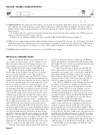
FRONT PANEL DESCRIPTION
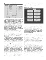
1. Signal/Overload. These multi-color LEDs indicate the presence of a significant audio Signal (green) or Overload conditions
(red). Both Input and Output indicators are provided for signal flow verification without a computer. The Inputs’ Signal
LEDs are driven from an analog comparator circuit prior to the input level control. All other LEDs are controlled from the
microprocessor.
The Output LEDs cycle yellow from left to right during power up and when the unit is loading a new DSP Program. All
outputs are muted during DSP Program changes.
If Output 1 or 2 is flashing, something has gone wrong. See TROUBLESHOOTING on page Manual-21.
2. COM (yellow, communications) flashes when a message for the unit is successfully received. This LED flashes often when
communicating with the computer, since metering messages are continually requested by the computer. The COM LED may
flash so often it may appear to be constantly on. There is also a brief flash whenever the Remote Switch Interface is used.
3. POWER indicates that the unit is connected to a powered RS 3 remote supply.
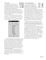
RPM 26 CONNECTION
When connecting the RPM 26 in your system, leave its
power supply and the amplifiers for last. This gives you a
chance to correct mistakes before damage is done to your
amps, speakers, ears, etc. Also, be sure to read the Important
Note in the QUICK START section on page Manual-1.
The RPM 26 has balanced Inputs and Outputs, with
shields connected to the chassis through three #4 serrated
screws on the rear. Keep these screws tight for the best
possible shield-to-chassis connections. The RS-232 cable
shields connect to the chassis through the four nuts and star
washers that the cable screws into. Be sure to screw down RS-
232 cables to guarantee good shield connections. The chassis
and the audio signal ground are connected together inter-
nally at the audio Input screw terminal. The RPM 26 chassis
connects through the RS 3 power supply cables to the earth
ground (3
rd
pin) of the 100 and 120 VAC line cords. A 6-32
screw and star washer are also provided on the unit’s rear if a
technical ground connection is needed. This chassis connec-
tion is also recommended for 230V operation. Connect the
non-inverting (positive) audio lines to the ‘+’ terminals, and
the inverting (negative) lines to the ‘–’ terminals. Connect the
cable shields to the center terminal on the Euroblock. For
those installations where the RPM’s internal shield-to-chassis
connection causes interference, connect the shields directly to
the chassis PEM nuts directly above each shield terminal. Be
sure to bite through the paint with the star washer and keep
the shields wrapped around the audio conductors as much as
possible. For the “theoretical” best ElectroMagnetic Interfer-
ence (EMI) immunity, connect the shields at both ends of the
cables. (For more information on System Connections, see
RaneNote 110, “Sound System Interconnection” later in this
manual or on Rane’s Internet Web site at www.rane.com.)
For those systems where Murphy and his EMI pests have
arisen or for those who wish not to tempt fate, the RPM 26
accepts optional line level input isolation transformers (Rane
part number 150-010). Call your nearest Rane dealer for more
information on the optional transformers.
To control the unit from a computer, use 9-pin RS-232
cables which are 50 feet or shorter. The cable and adapter
must not be a null-modem type. A short cable is supplied for
connecting adjacent units. Daisy-chain up to 250 units by
connecting the computer COM port to the RW 232 INPUT
connector on the first unit. Then connect the unit’s RW 232
OUTPUT connector to the next unit’s RW 232 INPUT.
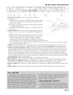
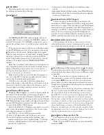
The DEVICE ADDRESS switch identifies each unit with
an ‘address’, and must be set uniquely for each unit. The
switches form a binary code from 0 through 255. Only the
numbers 1 through 250 may be used. The place values of
each switch are marked on the rear panel. The switch itself
may have numbers printed on it; these should be ignored. To
set a specific address, refer to the SETTING THE DEVICE
ADDRESS section on page Manual-22 or run the Address
Calculator software included with RaneWare.
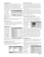
The REMOTE SWITCH INTERFACE (RSI) provides
contact closure control for up to eight preset memories. No
computer is required after the initial setup. There are nine
screw terminals; one is the common chassis ground (COM),
and the other eight are for Memories 1 through 8. Connection
of one of these to the COM terminal causes the unit to recall a
preset Memory. Multiple units may be controlled by connect-
ing these terminals in parallel. Either momentary or latching
switches may be used. A latching switch should only close
one contact at a time. If an RSI switch configuration changes
while the power is off, Memory recall results upon power-up
— since the RPM checks for changes to the RSI port each
time power is restored.


