


Manual-13
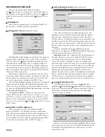
OUTPUT TRIM
The Output Trim looks, feels and acts in
much the same way as the Input Trim. So,
read the INPUT TRIM section on the previous
page for basic operating instructions. The two
Trims differ by the location on the screen, the
single
Output
Meter, the
Link
functionality
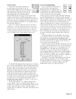
and, most importantly, their purpose. The Output Trim’s
purpose is to provide up to 30 dB of attenuation on each
output. This is useful to adjust for speaker sensitivity in both
distribution and crossover applications where each output
may require a slightly different level. Use the
Mute
button to
turn individual outputs off.
Since this is a digital attentuator and only the audio is
attentuated — noise is not attenuated, use the output Trim
sparingly since each dB of attenuation decreases the signal-
to-noise ratio. In extreme attenuation cases, it is better to
adjust the amplifier sensitivity controls for the best signal-to-
noise. The Output Trim’s detail window is shown here:
A/D, D/A AND METERING
Now, a word about metering and our
pal, the Windows operating system.
Displaying meters on computers poses a
unique problem for software designers and
sometimes for users, especially if you have
a “slow” computer. Everyone is familiar
with analog meters without computers deciding that display-
ing meter indicators needs to wait until a “more important”
task is completed. Windows provides the RPM 26 software an
update window opportunity every 100 milliseconds (10 times
per second). And, since there are more than just meters to
update, other functions at the computer’s discretion can have
a higher priority than the meters. This simply translates into
“the more meters you have on the screen, the more sluggish
and inaccurate they will appear.” For this reason, it is wise to
adjust the RPM’s
Trim
controls or view its meters one at a
time. This displays the least number of meter indicators on
the screen, making the display’s update rate as reliable as
possible.
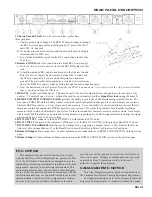
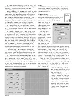
The
A/D
and
D/A
blocks on the RPM 26 Device Edit
screen indicate where in the signal chain the A/D and D/A
conversions occur. These blocks also contain the signal
present and overload indicators, all of which default to single,
two-color indicators: green for signal present, red for over-
load and gray for no signal detected.
Double clicking on any of the
A/D
or
D/A
blocks turns the
block into an eleven segment meter. On the A/D block, these
meter segments correspond to every third segment from the
A/D (dBFS)
meter. The segments on the
D/A
block also
correspond to every third segment from the
Output
meter.
The top segment lights at -2 dBFS, each subsequent segment
lights 3 dB before the segment above it. Again, to keep the
meters as reliable as possible, keep as few meter segments on
the screen as possible when adjusting levels.
The RPM 26’s front panel Input signal present LEDs are
familiar analog implementations. The remaining meters —
the input overload and all output meters — are microproces-
sor controlled but have a guaranteed update rate of 90
milliseconds, or just over 11 times per second.
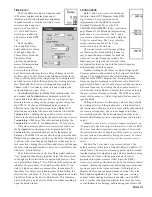
The
Output
Meter displays the voltage level at the output
screw terminal of the RPM 26 in dBu. The
Mute
button mutes
the given output. The
Invert
check box inverts the polarity of
the given output. When ramping is enabled, each time the
Invert
box is changed the given output’s level ramps to off ,
the polarity is inverted and the level ramps back up. Many
people frown upon purposely inverting the polarity of an
audio signal. The invert function here is provided solely as a
convenient tool for testing polarity. In permanent installations
it is always wise to correct polarity inversion problems
through other more permanent or “hardware” means such as
correcting cable-wiring errors.
The
Link
selection box “ties” groups of output Trim
controls together. There are 4 possible groups,
None
,
1
,
2
or
3
.
None
in the selection box indicates the given output is tied
with no other output. If two outputs’
Link
boxes share a
common value, for example
1
, then those two output trims are
linked together.


