Rane CP66 Installation Manual Download Page 3

CP66

Installation Manual

3

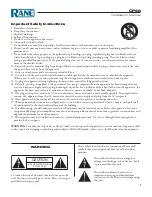
RISK OF ELECTRIC SHOCK

DO NOT OPEN

CAUTION

To reduce the risk of electrical shock, do not open the 

unit. No user serviceable parts inside. Refer servicing to 

qualified service personnel.

The symbols shown below are internationally accepted 

symbols that warn of potential hazards with electrical 

products.

This symbol indicates that a dangerous 

voltage constituting a risk of electric shock 

is present within this unit.

This symbol indicates that there are 

important operating and maintenance 

instructions in the literature accompanying 

this unit.

WARNING

Important Safety Instructions

1. Read these instructions.

2. Keep these instructions.

3. Heed all warnings.

4. Follow all instructions.

5. Do not use this apparatus near water.

6. Clean only with a dry cloth.

7. Do not block any ventilation openings. Install in accordance with manufacturer’s instructions. 

8. Do not install near any heat sources such as radiators, registers, stoves, or other apparatus (including amplifiers) that 

produce heat.

9. Do not defeat the safety purpose of the polarized or grounding-type plug. A polarized plug has two blades with one 

wider than the other. A grounding-type plug has two blades and a third grounding prong. The wide blade or third 

prong is provided for your safety. If the provided plug does not fit into your outlet, consult an electrician for replace-

ment of the obsolete outlet.

10. Protect the power cord and plug from being walked on or pinched particularly at plugs, convenience receptacles, and 

the point where it exits from the apparatus. 

11. Only use attachments and accessories specified by Rane.

12. Use only with the cart, stand, tripod, bracket, or table specified by the manufacturer, or sold with the apparatus. 

When a cart is used, use caution when moving the cart/apparatus combination to avoid injury from tip-over. 

13. Unplug this apparatus during lightning storms or when unused for long periods of time.

14. Refer all servicing to qualified service personnel. Servicing is required when the apparatus has been damaged in any 

way, such as power supply cord or plug is damaged, liquid has been spilled or objects have fallen into the apparatus, the 

apparatus has been exposed to rain or moisture, does not operate normally, or has been dropped.

15. The plug on the power cord is the AC mains disconnect device and must remain readily operable. To completely dis-

connect this apparatus from the AC mains, disconnect the power supply cord plug from the AC receptacle.

16. This apparatus shall be connected to a mains socket outlet with a protective earthing connection.

17. When permanently connected, an all-pole mains switch with a contact separation of at least 3 mm in each pole shall 

be incorporated in the electrical installation of the building. 

18. If rackmounting, provide adequate ventilation. Equipment may be located above or below this apparatus, but some 

equipment (like large power amplifiers) may cause an unacceptable amount of hum or may generate too much heat and 

degrade the performance of this apparatus.

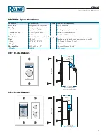
19. This apparatus may be installed in an industry standard equipment rack. Use screws through all mounting holes to 

provide the best support.

WARNING

: To reduce the risk of fire or electric shock, do not expose this apparatus to rain or moisture. Apparatus shall 

not be exposed to dripping or splashing and no objects filled with liquids, such as vases, shall be placed on the apparatus.

Summary of Contents for CP66

Page 1: ...are or a degree in rocket science Note If you have a PC you can take advantage of a few bonus features like Preset Saving and Custom Zone Nam ing by using the included Rane CP66 Software See Rane CP66...

Page 2: ...nd on the user is encouraged to try to correct the interference by one or more of the following measures Reorient or relocate the receiving antenna Increase the separation between the equipment and re...

Page 3: ...Rane 12 Use only with the cart stand tripod bracket or table specified by the manufacturer or sold with the apparatus When a cart is used use caution when moving the cart apparatus combination to avo...

Page 4: ...40 10 SIG OL LEVEL OFF 40 10 SIG OL LEVEL OFF 10 2 BAND EQ PAGE 1 SELECT 2 BAND EQ FILTER SIG OL LEVEL OFF 10 CHIME LEVEL L R SUM INPUT 6 PAGER 1 PAGER 2 CAT 5 3 BAND EQ ZONE 1 MONO ZONE 2 MONO ZONE 3...

Page 5: ...t with selectable 24 V phantom power and is assigned to Zones via a rear panel dipswitch Page 2 supports the optional Rane PAGER2 paging station allowing dynamic Zone selection right at the microphone...

Page 6: ...Page Page Active indicates that Page is currently active Settings Panes 6 r Each group of settings has a dedicated button to take you straight to the parameters you re interested in no menus to dig th...

Page 7: ...set to 2 over rides the other page if assigned to any of the same Zones If set to 2 while Page 1 is set to 1 Page 2 can still be overridden If both Page priorities are set to the same value the Pages...

Page 8: ...Soft ware on page 14 0 Front Panel Lock Connect L1 to ground to lock out all front panel settings as view only Connect L2 to ground to lock all front panel settings with the exception of Zone source...

Page 9: ...air is functioning the LED displays a solid green light Audio Rx lights steadily if the CP66 receive pair is working properly Audio Tx lights steadily if the CP66 transmit pair is working properly Com...

Page 10: ...roblem Unbalanced connections as found in RCA termi nals should be no longer than 10 feet 3 meters Consult the Sound System Interconnection RaneNote for help at http rane com note110 html Setup Proced...

Page 11: ...he Page 1 Zone Assign switch Rear Panel u A switch in the up position means that Zone will be paged 18 While paging adjust the Page Level Front Panel 8 for each Zone so it is at a comfortable level re...

Page 12: ...as well as non traditional setups Digital Remotes DR1 DR1 DR1 DR1 Volume Remotes Digital remotes are a very powerful addition to any system Install a DR1 into a party room or dining area up to 1 000...

Page 13: ...n of printed labels letting you set custom names for your Zones and Groups To easily make labels with any printer download the CP66 Labels PDF at rane com cp66 html A tool is included in the shipping...

Page 14: ...omatically establish a connec tion and show you the current configuration of the device When connected to a live unit the connection box turns green and displays the name and serial number of the devi...

Page 15: ...cially apparent when amount of noise near the page mic changes throughout the day mak ing it nearly impossible to find a threshold value somewhere near the middle that always works We recommend using...

Page 16: ...adjustable Input Mode Line Input Impedance 5 8k 10 Max Input Level 20 dBu Gain set to min Input Mode Mic Input Impedance 1 1k 10 Max Input Level 5 dBu Gain set to min Phantom Power 24 4 0 V 10 mA max...

Page 17: ...es in chassis allow securing to a table Size 4 5 H x 6 W x 2 D 11 5 cm x 15 3 cm x 5 1 cm Weight 20 ounces 567 grams Shipping Size 6 25 x 8 5 x 5 5 16 cm x 22 cm x 14 cm Weight 1 64 lb 745 grams 2 25...

Page 18: ...HEADROOM POWER POWER 6 12 3 12 6 3 0 0 6 12 3 0 1 2 dB MA 3 MULTICHANNEL AMPLIFIER 3 CHANNEL OUTPUT HEADROOM POWER POWER This example allows host paging in the dining room lounge meeting room patio r...

Page 19: ...ECT DR3 This car dealer has a time clock with a chime output connected to the PAGE 1 INPUT The clock has a contact closure that enables the chime Volume and ducking of background music are controlled...

Page 20: ...EQUIPMENT 24TJ R 4 3 2 1 ON 4 3 2 1 ON SCROLL PUSH TO SELECT DR3 DR1 DR1 DR1 DR1 BUSY CHIME READY FEED S FROM HOUSE CONSOLE MIX AND DIRECT OUTS ZONE 4 MT 4 MULTICHANNEL TRANSFORMER PAGE 1 PAGE 1 This...

Page 21: ...rconnections Grounding and EMC practices Shields of connectors in audio equipment containing active circuitry Rane s policy is to accommodate rather than dic tate However this document contains sugges...

Page 22: ...al grounding system improperly thus creating balanced equipment that is not immune to the cabling s noise currents This is one reason for the bad reputation sometimes given to bal anced interconnect A...

Page 23: ...n Figure 1b Recommmended practice CASE COMMON WRONG PRACTICE RECOMMENDED PRACTICE OPTIONAL CASE 1 2 3 3 1 2 CHASSIS GROUND SIGNAL GROUND CHASSIS GROUND CHASSIS GROUND Not using signal ground is the mo...

Page 24: ...consistent success indicates this and other acceptable solutions to RF issues exist though the increasing use of digital and wireless technology greatly increases the possibility of future RF problem...

Page 25: ...eferences 1 Neil A Muncy Noise Susceptibility in Analog and Digi tal Signal Processing Systems presented at the 97th AES Convention of Audio Engineering Society in San Fran cisco CA Nov 1994 2 Groundi...

Page 26: ...20 24 24 19 18 17 B B B B A A A A A A FEMALE BALANCED XLR NOT A TRANSFORMER NOR A CROSS COUPLED OUTPUT STAGE FEMALE BALANCED XLR EITHER A TRANSFORMER OR A CROSS COUPLED OUTPUT STAGE BALANCED TRS NOT A...

Page 27: ...RED SHIELD RED SHIELD SHIELD RED RED BLACK N C N C N C RED BLACK RED SHIELD N C BLACK RED BLACK RED 3 NC 2 RED 1 SHIELD 2 RED 1 SHIELD 3 BLACK 2 RED 1 NC 3 BLACK 2 RED 1 NC 3 BLACK 2 RED 1 SHIELD SHIE...

Page 28: ...3 BLACK 2 RED 1 SHIELD 3 BLACK 2 RED 1 SHIELD 3 BLACK 2 RED 1 SHIELD SHIELD BLACK SHIELD RED BLACK SHIELD RED BLACK RED SHIELD SHIELD BLACK RED SHIELD BLACK RED SHIELD BLACK RED SHIELD BLACK RED SHIE...

Page 29: ...F THIS LIMITED WARRANTY SHALL BE THAT WHICH IS DESCRIBED TO THE ORIGINAL RETAIL PURCHASER BY THE AUTHORIZED RANE DEALER OR DISTRIBUTOR AT THE TIME OF PURCHASE Rane Corporation does not however warrant...

Page 30: ...THE UNIT WAS PURCHASED OR if product was purchased in the U S AT THE RANE FACTORY IN THE U S If the product is being sent to Rane for repair please call the factory for a Return Authorization number...

Page 31: ...the manufacturer This declaration of conformity is issued under the sole responsibility of Rane Corporation Type of Equipment Professional Audio Signal Processing Model CP66 Immunity Results THD N re...

Page 32: ...C INPUT ENABLE AUDIO RX AUDIO TX COMM POWER LINK LINK LINK LINK LINK MASTER REMOTE REMOTE ZONE 6 REMOTE ZONE 5 REMOTE ZONE 4 REMOTE ZONE 3 REMOTE ZONE 2 REMOTE ZONE 1 PAGER 2 DIGITAL REMOTES ZONE OUTP...

Reviews: