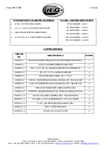
R&G LP0298BK Fitting Instructions Manual Download Page 7

Page 

7

 of 

15


LP0298BK 


R&G Racing 

Unit 1, She

lley’s

 Lane, East Worldham, Alton, Hampshire, GU34 3AQ 

Tel: +44 (0)1420 89007  Fax: +44 (0)1420 87301  
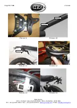
www.rg-racing.com

  Email: 

[email protected]


At this point, turn on the ignition and check all lights function correctly, if lights fail to 
illuminate, check connections. If indicators do not illuminate, swap the bullet connectors round. 


Mount the licence plate (it may require drilling) to the rear of the bracket ensuring that it does 
not cover the indicators. 


Refit all panels, the RHS footrest and the rider

s seat.  


IMPORTANT: IF FITTING A FULL-SIZE LICENCE PLATE AND PLACING IT FAR DOWN ON 
THE  LICENCE  PLATE  HANGER,  THERE  IS  A  SMALL  CHANCE  OF  THE  LICENCE  PLATE 
HITTING  THE  BACK  WHEEL  UNDER  HEAVY  LOAD  AND  OVER  LARGE  BUMPS  IN  THE 
ROAD.    IT  IS  YOUR  RESPONSIBILITY  TO  CHECK  FOR  THIS  POSSIBILITY  AND  TAKE 
AVOIDING ACTION.  FAILURE TO CHECK THIS COULD RESULT IN SERIOUS INJURY.


Depending on local laws, attach enclosed reflector 

(item 13)

 in an appropriate location. 


Please test the indicators, rear light, and licence plate illuminator before riding.


ISSUE 2

 - 16/06/2021 (TB) 


CONSUMER NOTICE 

The catalogue description and any exhibition of samples are only broad indications of the Products and R&G may make design 

changes which do not diminish their performance or visual appeal and supplying them in such state shall conform to the order. 

The Buyer acknowledges no representation or warranty (other than as to title) has been given or will apply to the Products other 

than those i

n R&G’s 

order or confirmation and the Buyer confirms it has chosen the Products as being of merchantable quality 

and  suitable  for  its particular  purposes.  Where  R&G fits  the  Products or  undertakes other  services  it  shall  exercise reasonable 
skill  and  care  and  rectify  any  fault  free  of  charge  unless  the  workmanship  has  been  disturbed.    The  Buyer  is  responsible  for 

ensuring that the warranty on the motorcycle is not affected by the fitting of the Products. On return of any defective Products 

R&G shall  at  its option  either  supply  a  replacement or refund  the  purchase  money but  shall  not be  liable  if  the  Products  have 

been  modified  or  used  or  maintained  otherwise  than  in  accordance  with  R&G

’s  or  manufacturer’s  i

nstructions  and  good 

engineering practice or if the defect arises from accident or neglect. Other than identified above and subject to R&G not limiting 

its liability for causing death and personal injury, it shall not be liable for indirect or consequential loss and otherwise its liability 

shall be limited to the amounts paid by the Buyer for the Products or the fitting or service concerned. These terms do not affect 

the Buy

er’s

 statutory rights. 


R&G RACING RETURNS POLICY (NON-FAULTY GOODS) 

Returns must be pre-authorised (if not pre-authorised the return will be rejected). Goods may only be returned direct to us if 

they  were  purchased  direct from  us  (customer  must prove  if  necessary).   Otherwise  to be returned  to original  vendor.  Goods 

must be in re-sellable condition, in the opinion of R&G Racing. All returns are subject to a 25% restocking and handling fee (25% 

of the gross value exc. P&P 

 at the prevailing price at time of purchase). The customer must pay any and all carriage charges. 

No returns of discontinued products, unless within 14 days of purchase. This policy does not affect your statutory rights and does 

not refer to faulty goods. 


Summary of Contents for LP0298BK

Page 1: ...OWN FOR CLARITY OF INSTRUCTIONS ONLY DO NOT PROCEED UNTIL YOU ARE SURE ALL PARTS ARE PRESENT PLEASE READ ALL INSTRUCTIONS BEFORE PROCEEDING IF IN ANY DOUBT WHEN FITTING OUR PRODUCTS CONSULT ONE OF OUR DEALERS OR HAVE FITTED BY A QUALIFIED TECHNICIAN PLEASE NOTE THAT THE WAY THE KIT IS PACKED DOES NOT NECESSARILY REPRESENT THE WAY OF MOUNTING TO THE BIKE IN THE EVENT OF RUBBER WASHERS BEING USED TO...

Page 2: ...O DESCRIPTION QTY ITEM 1 TB0298 WELDED ASSEMBLY 1 ITEM 2 LA0011 SMOKED TAIL LIGHT 1 ITEM 3 M8 x 1 25 x 55 00mm CAP HEAD BOLT TUBE MOUNTS 2 ITEM 4 M4 x 0 7 x 8 00mm COUNTERSUNK BOLT 2 ITEM 5 M8 WASHER OD 14mm 2 ITEM 6 150mm LENGTH OF 666 896 HEAT SHRINK THIN 6 ITEM 7 150mm LENGTH OF 666 919 HEAT SHRINK WIDE 2 ITEM 8 IWC0002 MINI INDICATOR WIRING COVER 2 ITEM 9 CON0072 INDICATOR TAIL LIGHT CONNECTOR...

Page 3: ...98BK R G Racing Unit 1 Shelley s Lane East Worldham Alton Hampshire GU34 3AQ Tel 44 0 1420 89007 Fax 44 0 1420 87301 www rg racing com Email info rg racing com EXPLODED ASSEMBLY VIEW FITTING PICTURES Picture 1 Picture 2 ...

Page 4: ...98BK R G Racing Unit 1 Shelley s Lane East Worldham Alton Hampshire GU34 3AQ Tel 44 0 1420 89007 Fax 44 0 1420 87301 www rg racing com Email info rg racing com Picture 3 Picture 4 Picture 5 Picture 6 Picture 7 Picture 8 ...

Page 5: ...K R G Racing Unit 1 Shelley s Lane East Worldham Alton Hampshire GU34 3AQ Tel 44 0 1420 89007 Fax 44 0 1420 87301 www rg racing com Email info rg racing com Picture 9 Picture 10 Picture 11 Picture 12 Picture 13 Picture 14 ...

Page 6: ...o the R G tail bracket using a 14mm spanner Fit the wiring covers item 8 to cover the securing nuts then fit a wiring extension item 10 to each indicator to give the correct wiring length If fitting R G mini indicators R G mini indicator product code RG374 for LED type or RG372 for Aero Style LED type secure to the R G tail bracket using a 13mm spanner then fit the wiring covers item 8 to cover th...

Page 7: ...as being of merchantable quality and suitable for its particular purposes Where R G fits the Products or undertakes other services it shall exercise reasonable skill and care and rectify any fault free of charge unless the workmanship has been disturbed The Buyer is responsible for ensuring that the warranty on the motorcycle is not affected by the fitting of the Products On return of any defectiv...

Page 8: ...DES INSTRUCTIONS NE PAS PROCEDER AU MONTAGE TANT QUE VOUS N ETES PAS SUR QUE TOUTES LES PIECES SOIENT PRESENTES VEUILLEZ LIRE TOUTES LES INSTRUCTIONS AVANT DE CONTINUER EN CAS DE DOUTE LORS DU MONTAGE DE NOS PRODUITS CONSULTEZ UN DE NOS REVENDEURS OU FAITES APPEL A UN TECHNICIEN QUALIFIÉ VEUILLEZ NOTER QUE LA FAÇON DONT LE KIT EST EMBALLE NE REPRESENTE PAS NECESSAIREMENT LA MANIERE DE LE MONTER SU...

Page 9: ...298 ASSEMBLAGE SOUDÉ 1 ARTICLE 2 LA0011 FEU ARRIÈRE FUMÉ 1 ARTICLE 3 M8 x 1 25 x 55 00mm BOULON SUPPORTS TUBE 2 ARTICLE 4 M4 x 0 7 x 8 00mm BOULON 2 ARTICLE 5 M8 RONDELLE OD 14mm 2 ARTICLE 6 150mm LONGUEUR DE 666 896 MANCHON THERMO RÉTRACTABLE FIN 6 ARTICLE 7 150mm LONGUEUR DE 666 919 MANCHON THERMO RÉTRACTABLE LARGE 2 ARTICLE 8 IWC0002 CACHE FIL DE MINI CLIGNOTANT 2 ARTICLE 9 CON0072 CONNECTEUR D...

Page 10: ...hoto 5 À l aide d une douille de 10 mm et d une clé retirez les 2x boulons de chaque côté du bras oscillant fixant le support arrière d origine comme indiqué sur la photo 6 puis retirez délicatement l ensemble de la moto Utilisez la clé pour retirer le siège puis connectez l adaptateur de câblage long article 9 au connecteur précédemment déconnecté Faites passer à travers le sous châssis de sorte ...

Page 11: ...to 10 Montez un capuchon article 14 à la tête de chaque boulon Tirez doucement le sous plateau vers le bas comme indiqué sur la photo 11 puis tirez l extrémité du métier à travers la découpe du sous plateau comme indiqué sur la photo 13 Connectez les connecteurs du métier à l adaptateur de câblage long installé précédemment dans l ordre suivant ORANGE CLIGNOTANT GAUCHE JAUNE OU ROUGE BLUE CLIGNOTA...

Page 12: ...FEN SIE ZUERST DASS ALLE TEILE VORHANDEN SIND LESEN SIE DIE MONTAGEANLEITUNG KOMPLETT DURCH BEVOR SIE ANFANGEN WENN SIE BEI DER MONTAGE DIESES PRODUKTES UNSICHER SIND BITTE EINEN UNSERER HÄNDLER KONTAKTIEREN ODER DAS KIT VON EINEM QUALIFIZIERTEN ZWEIRAD MECHANIKER MONTIEREN LASSEN DIE VERPACKUNG DER TEILE STELLT NICHT DIE REIHENFOLGE DER MONTAGE DAR HINWEIS FÜR KITS MIT PLASTIKUNTERLEGSCHEIBEN AN ...

Page 13: ...UNG MENGE ARTIKEL 1 TB0298 KENNZEICHENHALTER ZUSAMMENGESCHWEISST 1 ARTIKEL 2 LA0011 KENNZEICHENBELEUCHTUNG 1 ARTIKEL 3 M8 x 1 25 x 55 mm INBUSSCHRAUBE HALTERUNGEN 2 ARTIKEL 4 M4 x 0 7 x 8 mm SENKSCHRAUBE 2 ARTIKEL 5 M8 UNTERLEGSCHEIBE OD 14mm 2 ARTIKEL 6 150mm SCHRUMPFSCHLAUCHS DÜNN ART NR 666 896 6 ARTIKEL 7 150mm SCHRUMPFSCHLAUCHS BREIT ART NR 666 919 2 ARTIKEL 8 IWC0002 MINIBLINKER KABEL ABDECK...

Page 14: ...Benutzen Sie einen 10mm Steckschlüssel um die 2 Schrauben an beiden Seiten der Schwinge zu entfernen die den original Kennzeichenhalter befestigen wie in Abbildung 6 abgebildet dann entfernen Sie die komplette Einheit vom Motorrad Entfernen Sie den Sitz benutzen Sie den Schlüssel dann verbinden Sie den Adapter für die lange Verkabelung Artikel 9 mit dem zuvor getrennten Verbinder und dies durch de...

Page 15: ...ie untere Abdeckung vorsichtig nach unten ziehen wie in Abbildung 11 abgebildet dann ziehen Sie das Ende des Kabelstrangs durch den Ausschnitt in der unteren Abdeckung wie in Abbildung 13 abgebildet Verbinden Sie die Verbindungen für die Kabelstrang mit der zuvor montierten Adapter Verlängerung wie folgt ORANGE BLINKER LINKE SEITE GELB ODER ROT BLAU BLINKER RECHTE SEITE GELB ODER ROT GRÜN BREMSLIC...

Reviews: