background image

  HERCULES  50K       

5

Winch Operation  3

The best way to get acquainted with how your winch operates is to make test runs before you use 

it. Plan your test in advance. Remember, you hear your winch, as well as see it operate. Learn to 

recognize the sounds of a light steady pull, a heavy pull, and sounds caused by load jerking or 

shifting. Gain confidence in operating your winch and its use will become second nature with you.

The uneven spooling of cable, while pulling a load, is not a problem, unless there is a cable pileup 

on one end of drum. If this happens, reverse the winch to relieve the load and move your anchor 

point further to the center of the vehicle. After the job is done you can unspool and rewind for a 

neat lay of the cable.

CLUTCH OPERATION

To engage clutch:

1. Move the clutch control valve to the “clutch engaged” position.

2. Anytime the temperature is below freezing, run the motor in the “cable out” direction only until

    the drum starts to turn. In extreme cold temperatures (below 0° F/-18° C), pull out on the cable

    by hand only until the drum starts to turn.

3. Wait at least 3 seconds for the clutch to fully engage, after which the winch is ready to winch in   

    the cable.

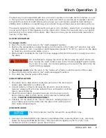
                                 Do not attempt to engage the clutch by first running the winch motor and

                                 then moving the clutch control valve to the “clutch-engaged” position while  

                                 the motor is running. Do not start picking up the load at the same time the   

                                 clutch is being engaged.

To disengage clutch: 

Run the winch in the “cable out” direction until the load is off the cable.

4. Move the clutch control valve to the “clutch-disengaged” position.

5. The cable may now be pulled off by hand.

CABLE INSTALLATION

1. This winch has a cable anchor located at each end of the drum which 

    allows cable installation on either end.

2. Unwind cable by rolling it out along the ground to prevent kinking. 

    Securely wrap end of wire rope opposite hook, with plastic or similar 

    tape to prevent fraying.

3. Insert the end of cable, opposite hook end, into the hole in drum 

    barrel. Secure cable to drum barrel, using setscrew furnished with 

    winch. 

TIGHTEN SETSCREW SECURELY.

4. Carefully run the winch in the “reel-in” direction. Keeping tension on 

    end of cable, spool all the cable onto the cable drum, taking care to 

    form neatly wrapped layers.

SYNTHETIC ROPE

                                 The roller tensioner must be removed to use synthetic rope.

1. Use only 12 strand (HMPE) high modulus polyurethane fiber coated synthetic rope, commonly 

    known as Dyneema (MBS 58,000 lbs.). Maximum Winch capacity is 250 ft. of 3/4” rope.  

2. Install and anchor synthetic rope as shown below. 

WARNING

NOTICE

Summary of Contents for Hercules 50K

Page 1: ...l Mailing Address P O Box 581510 Tulsa OK 74158697 Phone 918 438 2760 Fax 918 438 6688 www ramseyindustries com READ AND UNDERSTAND THIS MANUAL BEFORE INSTALLATION AND OPERATION OF WINCH SEE WARNINGS CAUTION Hercules 50K OM 914289 0918 B ...

Page 2: ......

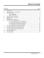
Page 3: ... Mounting Configuration L H High Angle Mounting Configuration R H Standard Mounting Configuration L H Standard Mounting Configuration 9 R H High Angle Mount Dimensional View L H High Angle Mount Dimensional View 10 R H Standard Mount Dimensional View L H Standard Mount Dimensional View 11 Winch Exploded View 12 Drum Assembly 13 Cable Tensioner SECTION PAGE 3 4 5 5 5 6 10 11 12 17 17 17 18 18 19 20...

Page 4: ...2 HERCULES 50K ...

Page 5: ...r load Stay out from under and away from raised loads Stand clear of cable while pulling Do not try to guide cable Do not exceed maximum line pull ratings shown in table Do not use winch to lift support or otherwise transport people A minimum of 5 wraps of cable around drum barrel is necessary to hold the load Cable anchor is not designed to hold load Use only Ramsey Winch recommended 3 4 syntheti...

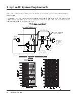
Page 6: ... 75 I D MINIMUM PORT CONTROL 25 GPM 2900 PSI PUMP 2 Hydraulic System Requirements Refer to the performance charts to properly match your hydraulic system to Hercules 50K winch performance 1 Line pull lbs first layer vs working pressure PSI and 2 line speed FPM first layer vs flow GPM Performance is based on a motor displacement of 11 9 cubic inches with 25 GPM maximum flow rate See page 10 for mot...

Page 7: ...t attempt to engage the clutch by first running the winch motor and then moving the clutch control valve to the clutch engaged position while the motor is running Do not start picking up the load at the same time the clutch is being engaged To disengage clutch Run the winch in the cable out direction until the load is off the cable 4 Move the clutch control valve to the clutch disengaged position ...

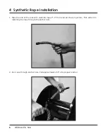
Page 8: ...pe Installation 1 Tape the end of the rope with electrical tape 2 3 from end as shown in picture This will aid in installing the rope through the anchor hole 2 Run rope through anchor hole Pull approximately 60 of rope past anchor ...

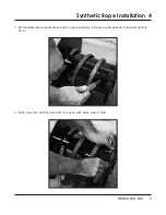
Page 9: ...ULES 50K 7 Synthetic Rope Installation 4 3 Spiral wrap rope around drum barrel approximately 3 times evenly spaced to second anchor hole 4 Push rope into anchor hole until it is even with back side of hole ...

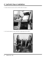
Page 10: ...8 HERCULES 50K 4 Synthetic Rope Installation 5 Tighten anchor set screw until it is flush with drum barrel 6 Pull excess slack from rope until rope is tight against drum barrel ...

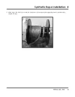
Page 11: ...HERCULES 50K 9 Synthetic Rope Installation 4 7 Wind rope onto drum no load for minimum of 8 wraps before applying load to install entire length of rope ...

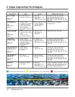
Page 12: ...TRANDS EXTREME STIFFNESS UNCHANGED BY FLEXING EXPOSURE TO EXCESSIVE HEAT SHOCK LOAD OR A SUSTAINED HIGH LOAD IF POSSIBLE REMOVE AFFECTED SECTION AND RESPLICE WITH A STANDARD END FOR END SPLICE IF RESPLICING IS NOT POSSIBLE RETIRE THE ROPE DISCOLORATION DEGRADATION REPAIR OR RETIRE FUSED FIBERS BRITTLE FIBERS STIFFNESS CHEMICAL CONTAMINATION IF POSSIBLE REMOVE AFFECTED SECTION AND RESPLICE WITH A S...

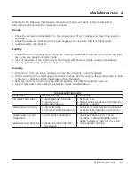
Page 13: ...r more often if winch is used frequently 2 Fill the winch to the oil level plug with clean kerosene Run the winch a few seconds with no load in the reel in direction Drain the kerosene from the winch 3 Refill the winch to the oil level plug with all purpose SAE 75W 90 synthetic gear oil 4 Inspect frame and surrounding structure for cracks or deformation TROUBLESHOOTING GUIDE CONDITIONS POSSIBLE CA...

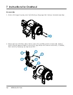
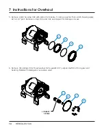
Page 14: ...lugs 42 Remove tensioner assembly 2 Disconnect hose 50 from elbow 43 on valve 51 and fitting 29 on brake 36 Remove motor 39 and gasket 36a by removing 2 cap screws 20 Remove valve 51 if needed from motor by loosening 4 cap screws 14 36a 39 51 14 20 43 50 42 7 Instructions for Overhaul ...

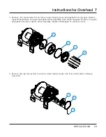
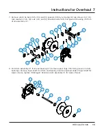
Page 15: ... from ring gear Remove input thrust washer sun gear and input carrier assembly from inside ring gear Remove ring gear and gasket Remove output carrier assembly Replace if damaged or excessive wear 4 Remove 8 cap screws 18 to remove clutch retainer plate 10 from clutch piston Remove clutch 9 37 37 4 16 9 10 18 ...

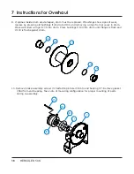
Page 16: ...om clutch housing apply air to 1 8 port Remove o rings 40 and 41 and inspect for damage or wear 6 Remove 9 springs 49 thrust washer 25 gasket 37 output shaft 12 from gear end bearing Replace if damaged or excessive wear 41 29 40 28 12 25 37 49 LONGEST SPLINE 7 Instructions for Overhaul ...

Page 17: ...ar end bearing 6 from drum assembly 1 8 Pull drum assembly 1 from end bearing 7 Remove quad rings 34 from grooves in drum bushings Remove input shaft 13 from end bearing Examine splined ends of input shaft for signs of wear replace if damaged Examine drum assembly 1 for signs of wear 27 26 45 46 24 23 1 23 24 46 26 27 27 26 44 46 24 23 24 46 26 27 23 6 48 5 53 7 8 2 13 34 1 34 ...

Page 18: ... in drum Place well oiled o rings 106 into drum Press bushings 104 into drum until flange is flush and 103 is flush against drum 10 Remove brake assembly screws 15 attaching brake 36b to end bearing 7 Remove gasket 36d from end bearing Take note of mounting configuration for proper mounting of parts during re assembly 103 105 101 105 104 15 36c 36b 36d 11 7 7 Instructions for Overhaul ...

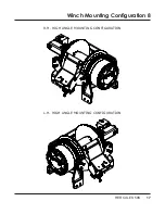
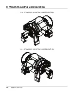
Page 19: ...HERCULES 50K 17 Winch Mounting Configuration 8 R H HIGH ANGLE MOUNTING CONFIGURATION L H HIGH ANGLE MOUNTING CONFIGURATION ...

Page 20: ...18 HERCULES 50K 8 Winch Mounting Configuration R H STANDARD MOUNTING CONFIGURATION L H STANDARD MOUNTING CONFIGURATION ...

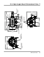
Page 21: ...EL PUSH ON FITTING FOR 1 4 DIAMETER TUBING AIR PRESSURE FOR TENSIONER 140 PSI MAX 90 PUSH ON FITTING FOR 1 4 DIAMETER TUBING PRESSURE PORT 100 TO 120 PSI FOR DISENGAGING CLUTCH DEUTSCH CONNECTOR 12V DT06 2S FOR HIGH SPEED LOW TORQUE CABLE IN STATIC LOAD HOLDING BRAKE FOR DRUM 2 PLACES ADJUSTABLE DRAG BRAKE 1 13 28 6 TYP Ø 91 23 CABLE ANCHOR 2 PLACES Ø 81 20 6 THRU 4 PLACES EACH SIDE 18 25 463 5 DR...

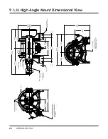
Page 22: ...SURE PORT 100 TO 120 PSI FOR DISENGAGING CLUTCH DEUTSCH CONNECTOR 12V DT06 2S FOR HIGH SPEED LOW TORQUE STATIC LOAD HOLDING BRAKE CABLE IN ADJUSTABLE DRAG BRAKE FOR DRUM 2 PLACES 90 SWIVEL PUSH ON FITTING FOR 1 4 DIAMETER TUBING AIR PRESSURE FOR TENSIONER 140 PSI MAX 1 13 28 6 TYP Ø 81 20 6 THRU 4 PLACES EACH SIDE Ø 91 23 CABLE ANCHOR 2 PLACES 12 12 308 0 21 25 539 7 Ø18 25 463 5 DRUM FLANGE 9 L H...

Page 23: ...ARREL 21 25 539 8 12 13 308 0 SPRING ASSIST AIR ROLLER TENSIONER ADJUSTABLE DRAG BRAKE FOR DRUM 2 PLACES CABLE IN 1 4 SPADE 12V FOR HIGH SPEED LOW TORQUE 10 SAE O RING PORTS 7 8 14UNF 2B THREAD TYP BOTH SIDES 1 8 27NPT PRESSURE PORT 100 TO 120 PSI FOR DISENGAGING CLUTCH Ø 81 20 6 THRU 4 PLACES EACH SIDE HOLDING BRAKE STATIC LOAD 2 PLACES CABLE ANCHOR 91 23 140 PSI MAX AIR PRESSURE FOR TENSIONER FO...

Page 24: ...08 0 Ø7 00 177 8 DRUM BARREL Ø 91 23 CABLE ANCHOR 2 PLACES SPRING ASSIST AIR ROLLER TENSIONER Ø 81 20 6 THRU 4 PLACES EACH SIDE 1 8 27NPT PRESSURE PORT 100 TO 120 PSI FOR DISENGAGING CLUTCH PUSH ON TYPE SWIVEL FITTING FOR 1 4 DIAMETER TUBING AIR PRESSURE FOR TENSIONER 140 PSI MAX 10 SAE O RING PORTS 7 8 14UNF 2B THREAD TYP BOTH SIDES 1 4 SPADE 12V FOR HIGH SPEED LOW TORQUE ADJUSTABLE DRAG BRAKE FO...

Page 25: ...FOR ILLUSTRATION ONLY 10 40 9 29 41 49 37 25 12 47 18 28 37 33 54 37 4 52 16 38 42 27 26 46 24 23 6 43 23 24 27 26 27 3 21 34 13 8 48 53 5 22 17 22 17 2 11 36a 39 36 51 31 14 43 32 50 20 29 15 36c 36d 36b 26 45 45a 46 23 24 24 23 34 1 7 46 44 26 27 LONGEST SPLINE ...

Page 26: ...BOLT 1 4 20NCX1 2 FLAT SOCHD ND STP 19 N A 20 2 414948 CAP SCREW 1 2 13NCX1 1 4LG SOCKET HD 21 2 416072 SET SCREW 1 2 13NCX3 4LG HXSOCHD CUP 22 2 418098 NUT 3 4 16NF HEX JAM 23 8 418099 NUT 3 4 10NC HEX REG ZINC PLATED 24 8 418249 LOCK WASHER 3 4 ID MED SECT ZINC PLT 25 1 418520 WASHER THRUST HDP40 50 26 4 418555 SHOULDER BOLT 1 2 X 1 1 4 Z P 27 8 420030 CAP SCREW 3 4 10UNC X 3 LG HX HD GR 8 Z P 2...

Page 27: ...MTG 45a 1 474245 TIE PLATE FOR SPECIAL MOUNTED TENSIONER HERC 50K 46 4 474246 SPACER TIE PLATE HERC 50K 47 1 490072 RING RETAINING EXTERNAL 48 2 494002 SPRING QQ W 428 TYPE I MUSIC WIRE 49 9 494140 SPRING HDP40 50 LEE SPRING LC085J06 50 1 509139 HOSE 4 4 90 DEG 37 DEG FLARE 13 39 INCH 51 1 516024 VALVE MTR CONTROL 24V 51a 1 516025 VALVE MTR CONTROL 12V 52 1 518027 THRUST DISC 035X 922DIA ALL PLANE...

Page 28: ...SCRIPTION 1 1 234248 DRUM ASSEMBLY FABRICATED SHORT HDP 50 2 2 416072 SET SCREW 1 2 13NCX3 4LG HXSOCHD CUP 3 1 412078 BUSHING DRUM SAE 660 BRZ IPH 45000 4 1 412079 BUSHING DRUM SAE 660BRZ 4 3 8IDX3LG 5 2 462043 O RING AS 568 348 3 16X4 3 4X4 3 8 1 5 5 3 4 2 ...

Page 29: ...HERCULES 50K 27 4 18 18 8 5 12 12 5 8 13 13 2 15 16 7 1 7 17 3 6 6a 14 9 9 11 10 10 11 Cable Tensioner 13 ...

Page 30: ... 2 354067 ROLLER SHORT 6 1 408453 BRACKET 6a 1 408452 BRACKET STANDARD 7 2 412108 BUSHING 8 2 412178 TENSIONER BUSHING 9 2 414316 CAP SCREW 3 8 X 1 1 4 10 2 418045 NUT 3 8 11 2 418177 LOCK WASHER 3 8 12 2 420031 CAP SREW 13 2 424005 COTTER PIN 14 1 432041 FITTING AIR 15 1 433036 AIR CYLINDER 16 1 468002 REDUCER BUSHING 17 1 494155 SPRING 18 2 518100 WASHER ...

Page 31: ...rized by Manufacturer or for equipment misused neglected or which has not been installed correctly RAMSEY WINCH shall in no event be liable for special or consequential damages RAMSEY WINCH makes no warranty in respect to accessories such as being subject to the warranties of their respective manufacturers RAMSEY WINCH whose policy is one of continuous improvement reserves the right to improve its...

Page 32: ...HERCULES 50K ...

Reviews: