ICI16• 15
Apply 5V DC to pins 1 and 2 on header J2. Pin 1 is denoted with a triangle
symbol. Install included header jumper between pins 2 and 3 to select IR
mode. You are now ready to program your ICI16.
PROGRAMMING YOUR ICI16
Remember to install some fresh batteries in your remote control, and aim
the infrared LED towards the photo sensor. Set switch 8 on S2 down, set the
others up. Switch 1 is the switch nearest to R1 on the PC board. Switch 8 is at
the other end. Depress any button you want to use on your remote control.
The LED should begin to blink as the unit receives the infrared code from the
transmitter. This testing verifies the operation of the detector and associated
circuitry. It will also provide some clues to the operation of the remote control
unit (remember we talked about this in the theory of operation) as you may
see a long “burst” of code followed by successive shorter pulse trains, or you
may see the pulse train being repeated over and over. If you have access to
an oscilloscope you can even observe this pulse train on the detector “output
“pin, which is tied to pins 1 and 19 of the microcontroller.
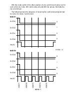
Now we will set our controller to the “learn” mode to memorize the pulse
trains from our remote, and configure the switch S2 to learn 16 codes as we
move along. The controller is placed into learning mode by setting the first
switch in the S2 switch block to “1” (down). Now the unit is waiting to
memorize the code for your remote. Depress the button on your remote
control unit and the LED on the front panel will blink. Just to be safe, push the
button on your remote control unit twice to ensure that the micro has
memorized your remote control’s pulse train. You may continue to program up
to 15 more buttons.
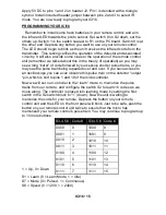
0000 0
1000 8
0001 1
1001 9
0010 2
1010 10
0011 3
1011 11
0100 4
1100 12
0101 5
1101 13
0110 6
1110 14
0111 7
1111 15
S3,4,5,6 Code #
S3,4,5,6 Code #
1 = Up, 0 = Down
S1 = Learn (0 = Learn Mode, 1 = Idle)
S7 = Mode (0 = Pulsed, 1 = Continuous)
S8 = Speed (0 = 1200, 1 = 2400)


