Issue A Nov 2011
Page 3 of 5
Apply Power to the system
The WAVFR takes its power from the RAKO wireless network. No other power supply is required.
Connect WAVFR by CAT5, or RJ11 to the wired system and power up.
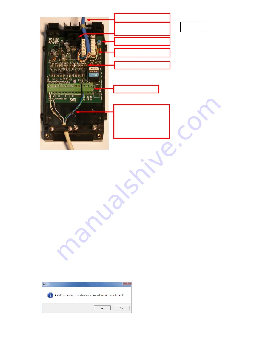
Two LEDs will light on the WAVFR circuit board. The
“
Power
”
LED next to the RJ11 indicates that
correct volts are being received from the system. The LED
“
D25
”
near the terminal blocks shows that
the WAVFR on-board supplies are healthy.
Configure the WAVFR using RASOFT
For WAVFR to operate correctly with a RAKO system some initial setup must be performed. This is
done using a PC running RASOFT software and communicating with the Wired System via a RAKO
Bridge Product (WRE-Bridge, WA-Bridge of WTC-Bridge).
Open the Project File for the installed Rako system.
Make sure that Rasoft is talking to the system
through a Bridge
–
Do not try to use RAUSB, RAH-Smart, RAV232 to make the connection. (Refer to
the Bridge User Instructions or the
Wired System Programming Guide
for assistance).
Press and Hold the WAVFR Setup Switch
. After a few seconds the WAVFR will enter Setup Mode
and LED
’
s A,B,C,D,E on the WAVFR will start to blink.
A Message will pop up in Rasoft to acknowledge
that the WAVFR is in Setup Mode.
Press the
Yes
button to continue.
Connect each remote input to one
of the terminals A-J.
Connect a return/ground wire
from each remote input to one of
the COM terminals
CAT5 Cable to Rako Wired system
RJ11 socket for direct connection
to a RAK-Link, RAK-Star or WP-Con
Inputs Indicator LED’s
Volt Free/Logic Inputs
Punch Down Daughterboard
Pushbutton Setup Switch
Figure 3


