background image

30

ENGLISH                   RAIS - Manual for RAIS RIVA                                

Spare part drawing - RAIS RIVA

Pos./Ref.        Quantity                       Part no./description

       1   


          410060190/95


                  Top plate without hole

       2   


          410060290/95


       Top plate with hole

       3   


           2101090/95


                 Door

       4   


             2100990


           Air-system

       5   


             2102200


         Firebrick set

       6   


             2105500


              Seal set

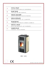
Summary of Contents for Riva

Page 1: ...1 ENGLISH RAIS Manual for RAIS RIVA U S E R M A N U A L RAIS RIVA ...

Page 2: ...We cannot be held responsible for any misprints ...

Page 3: ... CASE OF COMBUSTIBLE WALL 16 GENERAL INSTALLATION NON COMBUSTIBLE WALL 17 FOR THE INSTALLER 18 OPERATING INSTRUCTIONS 19 FUEL 19 20 DRYING AND STORAGE 20 REGULATION OF COMBUSTION AIR 21 ROOM VENTILATION AND STOVES 21 USING THE WOOD BURNING STOVE 22 ADJUSTMENT OF AIR DAMPER 22 CONTROL 22 FIRST USAGE 23 LIGHTNING AND FUELLING 24 25 CLEANING AND CARE 26 CLEANING OF THE FLUE WAYS 27 INTERRUPTION OF OP...

Page 4: ...lling and using it In the case of warranty coverage and for general queries regarding your wood burning stove it is important that you know the stove s production number We therefore recommend that you note down the number in the table below The pro duction number is located on the back of the stove at the bottom Warranty Your RAIS wood burning stove comes with a 5 year warranty The warranty howev...

Page 5: ...3 838 Combustion chamber s width depth height mm 360 240 380 Recommended amount of wood when fuelling kg Distributed on 2 3 logs of wood of approx 25 cm 1 6 Min uptake Min draught Pascal 12 Weight kg 138 Smoke gas mass flow g s 6 4 Smoke gas temperature C 250 Intermittent operation Fuelling should should be under taken within 3 hours Specifications ...

Page 6: ...ughout the entire room The cold air is sucked in at the base of the stove up through the convection channel which runs along the stove s combustion chamber The heated air pours out at the top of the stove which ensures a circulation of warm air throughout the room The stoves are equipped with a cold lever RAIS special feature which means you could almost do away with gloves Be aware however that a...

Page 7: ...and Safety at Work Act 1974 It is the responsibility of the installer to ensure that all requirements of this Act are met during the installation works Attention is drawn in particular to the following Handling The appliance is a heavy item and adequate facilities must be available for loading unloading and site handling Fire Cement Some types of fire cement are caustic and should not be allowed t...

Page 8: ...lations Approved Document J Any existing chimney must be clear of obstruction and have been swept clean immediately before installation of the stove If the stove is fitted in place of an open fire then the chimney should be swept one month after installation to clear any soot falls which may have occurred due to the difference in combustion between the stove and the open fire If there is no existi...

Page 9: ...le soot door or doors must be provided for sweeping the chimney and connecting fluepipe You should also familiarise yourself with the draught conditions for chimneys with 2 flues The flue outlet spigot is 150 mm in diameter For strong draughts the chimney or flue should be fitted with a draught stabiliser In which case it is important to ensure that there is a free flow through area of minimum 20 ...

Page 10: ...cture must be able to carry the weight of the wood burning stove as well as the weight of a chimney if necessary When you choose where to set up your RAIS wood burning stove you should consider the heat distribution to the other rooms This will enable you to get the best use out of your stove The stove should be set up at a safe distance from inflammable materials See the manufacturer s plate on t...

Page 11: ...pcs M6 nuts by a wrench Mount the smoke discharge socket which is found in a bag in the stove and the clamp for the upper smoke conductor with three M6x20 cylinder screws and M6 nuts Mount the upper smoke conductor smoke converter plate and top plate in reverse order Remove the blank flange and the packing and posi tion them in the hole at the top See to it that the pack ing is positioned correctl...

Page 12: ... the specified distance to the floor A normal screw to be put in the wall through the centerhole The top of the bracket to be horizontal Reflektoplade placeres på vægbeslag Røgafgangen ændres om nødvendigt se seperat afsnit og røgstuds monteres Friskluftsforbindelsestilbehør monteres under oven se seperat vejledning hvis dette er nøgvendigt The holes in the wall to be drilled through the holes in ...

Page 13: ...n the pictures to align the burning chamber relative to the wall The burning chamber without door or panels are lifted on to the bracket on the wall Flue connector and eventually fresh air connection are connected before the burningchamber are pushed to it correct position Fastening bolts are mounted and loosely tight ened Fastening bolts are tightened firmly ...

Page 14: ...A Sidepanels are lifted on to the guides in the bottom The distance between the side panels and the fron panel to be equal in both sides The front cover are mounted and fastened by two nuts Sidepanels are fastened in the top by two bolts ...

Page 15: ...wo bolts The top plate in put on and the door is carefully installed again For top connected stoves the flue pipe in in stalled The stove is finished Check the full functional ity of the door and air control The sweeper to check and approve the stove before using the stove ...

Page 16: ...earth of a size and construction that is in accordance with the provisions of the current UK Building Regulations Approved Document J If the stove is to be installed on a wooden floor it must be covered with a noncombustible material at least 12mm thick in accordance with UK Building Regulations Approved Docu ment J to a distance of 300 mm in front of the stove and 150 mm to each side measuring fr...

Page 17: ...urniture 1000 mm Distance to flammable materials B in front floor 300 mm C to the side floor 150 mm D to the side of the wall 350 mm E to the floor 200 mm F to the ceiling 1000 mm C C B A D E D F Using not insulated smoke pipe the minimum distance to combustible wall must be 225 mm from smoke pipe ...

Page 18: ... connections to the chimney Ensure that the appliance and chimney flue are functioning correctly before finally handing over to the user If necessary read the later parts of this manual for guidance on care required when first lighting Inform the user that the appliance has been commissioned and ready to use and give in struction on the safe operation of the stove These Instructions must be left w...

Page 19: ...east one surface area free of bark We do not recommend stoking with painted laminated or impregnated wood wood with a synthetic surface painted refuse wood chipboard plywood domestic waste paper bri quettes and pit coal as this will produce malodorous smoke which could be poisonous When firing with the above mentioned items and amounts larger than those recommend ed the stove is subjected to a lar...

Page 20: ...of wood type 1 kg beech merely takes up less space than 1 kg of fir Drying and storage Drying wood takes time proper air drying takes approx 2 years Here are some tips Store the wood sawn split and stacked in an airy sunny place which is protected against rain the south side of the house is particularly suitable Store the firewood stacks at a hand s breadth apart as this ensures that the air flowi...

Page 21: ...al gas residues By setting the interval between position 1 and 2 the energy content in the firewood is used optimally as there is oxygen for combustion and for the burning of the pyrolysis gasses When the flames are a clear yellow the damper has been set correctly Finding the correct position comes with time after you have used for stove for a while It is not recommended that you turn it down comp...

Page 22: ...minimal air intake Position 2 Push the handle towards the right until it stops This position provides full secondary air intake In the event of ordinary combustion the handle is to be adjusted to the interval between 1 and 2 When the flames are clear and yellow the damper has been adjusted correctly resulting in slow optimal combustion Position 3 Lift the handle up and push it towards the right Th...

Page 23: ...he stove gets very hot when in use always wear protective gloves when tending the stove If the stove has not been used for a while follow the steps as if you were using it for the first time IMPORTANT Warning Note Properly installed operated and maintained this appliance will not emit fumes into the dwelling Occasional fumes from de ashing and re fuelling may occur However persistent fume emission...

Page 24: ...om the chimney it is advisable to place a screwed up piece of newspaper between the upper baffle plate and the chimney set the paper on fire and wait until you hear a rumbling noise in the chimney This means that there definitely is a draught in the chimney and you avoid smoke in the room To light the stove use alcohol briquettes or similar as well as approx 2 kg of firewood split into kin dling s...

Page 25: ... of glowing embers add 2 3 pieces of wood Leave the door ajar until the fire has caught on properly close the door Damper see adjustment of air damper After approx 5 min or when the flames are clear and stable close the damper gradually It is recommendable to have a layer of ash of ap prox 20 mm as it has an insulating effect Note During operation the door should always remain shut ...

Page 26: ...ion chamber Scrape shovel the ash out and store it in a non flammable container until it has cooled down You can dispose of ash with your normal household waste REMEMBER Never remove all the ashes from the combustion chamber the wood will burn at its best with a layer of ashes of approx 20 mm Prolonged periodes of non use If the stove is to be left unused for a prolonged period of time then it sho...

Page 27: ...e slantwise Pull out the plate carefully Then remove the smoke conductor by lifting it up and moving it forward Carefully lift out the smoke conduc tor Remove dirt and dust and mount the parts in reverse order The flue way consist of a smoke converter plate and smoke conductor Both parts are made of vermaculit Handle these parts carefully ...

Page 28: ...al chimney draught too large 22 Pa draught control regulator should be installed A stove burning too weakly could be caused by too little firewood too little air supply for room ventilation unclean smoke channels leaky chimney leakage between chimney and flue If your stove continues to malfunction we recommend that you contact your RAIS dis tributor or chimney sweep IMPORTANT To ensure safe burnin...

Page 29: ...es and spare parts If spare parts other than those recommended by RAIS are used the warranty is voided All replaceable parts can be bought as spare parts from your RAIS distributor See the following spare parts diagrams for the individual products ...

Page 30: ...IVA Spare part drawing RAIS RIVA Pos Ref Quantity Part no description 1 1 410060190 95 Top plate without hole 2 1 410060290 95 Top plate with hole 3 1 2101090 95 Door 4 1 2100990 Air system 5 1 2102200 Firebrick set 6 2105500 Seal set ...

Page 31: ...31 ENGLISH RAIS Manual for RAIS RIVA 2 1 5 3 4 6 ...

Page 32: ...RAIS A S Industrivej 20 DK 9900 Frederikshavn www rais dk ...

Reviews: