background image

WS PRO LT weather station

8

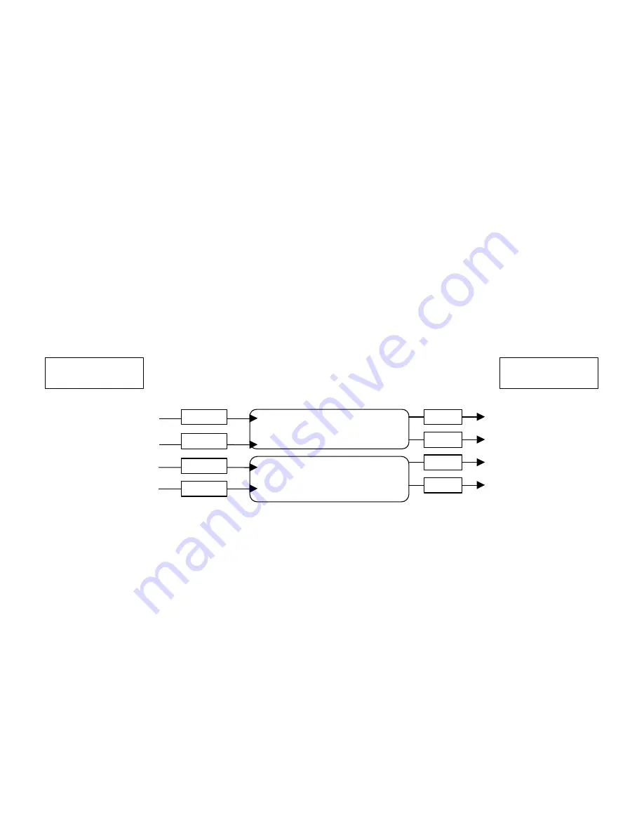
Communication Wiring Setup for Direct Connect Weather Stations

1.


Furnish and install a Belden #9883 Direct Burial Type, communication cable between the weather
station and the central control computer (not to exceed 20,000 ft. / 3.8 miles)

Note: The Belden cable should consist of three (3) twisted pairs of wires (20 gauge), a bare copper drain
wire and an aluminum shield. The three (3) twisted pairs shall be color coded as follows: one (1) black and
green pair, one (1) black and red pair, and one (1) black and white pair

At the weather station…

2.


Connect the Black (-xmt) and Green (+xmt) pair of wires (of the communication cable) to the Black
and Red wires respectively on the Line end of the first MSP-1

3.


Connect the Black and Red wires on the Equip end of the first MSP-1 to the White (-xmt) and Green
(+xmt) wires of the cable (9720) furnished with the weather station

4.


Connect the Red (+rcv) and Black (-rcv) pair of wires (of the communication cable) to the Red and
Black wires respectively on the Line end of the second MSP-1

5.


Connect the Red and Black wires on the Equip end of the second MSP-1 to the Red (+rcv) and Black (-
rcv) wires of the cable (9720) furnished with the weather station

6.


Ground the bare copper drain wire of the Belden cable to the grounding rod using a brass ground wire
clamp.

Note: Do not ground the drain wire at the central end of the cable. Leave it unused.

7.


Leave the Black and White pair of wires as spares

8.


Connect the other end of the cable (9720) to the 

Computer

 connection on the white box (containing

RAD modem)

9.


Connect the RS232 end of the second cable (9721) to the RS232 port of the weather station

10.


Connect the other end of the cable (9721) to the 

WX Station

 connection on the white box

11.


Install the white box just below the weather station using furnished U bolt

LINE

MSP-1

EQUIP

LINE

MSP-1

EQUIP

Black

Red

Red

Black

Black

Red

Red

Black

White (-xmt)

Green (+xmt)

Red (+rcv)

Black (-rcv)

Black (-xmt)

Green (+xmt)

Red (+rcv)

Black (-rcv)

Communication Wire

from Central

Communication Wire at

Weather Station

Summary of Contents for WS PRO LT

Page 1: ...WS PRO LT Weather Station Installation Manual ...

Page 2: ......

Page 3: ...the battery a solar panel or a user supplied external DC power source that has a nominal rating of 18 V at 1 amp output is required Site Selection The ideal site is representative of the general area is level and well away from obstructions such as buildings trees and steep slopes If obstructions exist use the Ten Times the Height Rule which is illustrated in Figure 1 Figure 1 Ten Times the Height...

Page 4: ...de a second spread spectrum radio that is installed at the central control computer To test the radio transmission of your weather station carry the weather station to the site then attempt to communicate with the central control computer If obstructions in the line of sight are preventing the weather station from communicating try the following Relocate your weather station away from obstructions...

Page 5: ...mmunications cable 9 pin to 9 pin X X X X X 3 Two keys X X X X X 4 RF 400 series Spread Spectrum Radio X X 5 RF415 series Spread Spectrum Radio X 6 Antenna X X X whip antenna 7 RFXXX AC Adapter X X X 8 Solar Panel X X X 9 Solar Panel Mounting Hardware X X X 10 RAD Modem for computer X X 11 RAD modem in white box for weather station X X 12 Cable for connection between weather station and RAD modem ...

Page 6: ... to computer serial COM port 5 Connect power to the weather station i e solar power user supplied DC power 6 Turn the key to the ON position Weather Station Configuration 1 Request Automatic ET and Multiple Weather Stations module keycodes from Global Service Plan GSP or from your local Rain Bird distributor 2 Start Rain Bird central control software i e Cirrus NimbusII or StratusII 3 Enter your k...

Page 7: ...4 Weather Station Configuration 9 Select Station Type Rain Bird Turf CR200 10 Enter latitude and elevation where weather station will be installed 11 Assign port by clicking on Test and Set Port see Figure 5 Figure 5 Test and Set Port 12 Select weather station 13 Select COM Port assign to available COM port 14 Click Assign button 15 Click OK button 16 Enter download time 17 Repeat steps 8 16 for 2...

Page 8: ... Antenna 2 Connect the serial cable male connector to the radio connector labeled PWR TW RX 3 Connect the serial cable female connector to a computer serial COM port 4 Plug the RFXXX AC adapter to the RFXXX connector labeled DC Pwr input 5 Plug the other end of the RFXXX AC adapter into a grounded AC wall outlet The red Pwr Tx status light should illuminate 6 Click on Weather Program button Note T...

Page 9: ... pair of wires of the communication cable to the Red and Black wires respectively on the Line end of the second MSP 1 5 Connect the Red and Black wires on the Equip end of the second MSP 1 to the Red rcv and Black rcv wires of the cable 9720 furnished with the weather station 6 Ground the bare copper drain wire of the Belden cable to the grounding rod using a brass ground wire clamp Note Do not gr...

Page 10: ...y 14 Connect the RAD modem to a COM port on your computer it might be necessary to use a 9 to 25 pin adapter Installation Procedure 1 Mount a mast pole 1 25 OD and 8 to 10 feet 312 cm high on cement base 2 Place your weather station assembly on top of the mast pole with the base firmly seated on the top edge of the mast pole of see Figure 6 3 Loosely tighten the U bolt nuts so that the weather sta...

Page 11: ...evel on top of the weather station see Figure 9 Minor adjustments can be made by placing shims between the weather station base and the top of the pole 7 Connect the power source that will recharge the internal sealed rechargeable battery For Solar Powered weather stations follow instructions below 8 Remove the red cap from the solar radiation sensor Figure 10 Bull s level Figure 9 Bull s Level on...

Page 12: ...her station internal battery It has a 72 sq inch surface area and produces 5 watts at a peak of 17 1 volts Figure 11 5W Solar Panel 1 Place the solar panel on the mast below the station to the maximum distance allowed by the solar panel cable 2 Loosely tighten the U bolt so that the solar panel is stable but can be rotated on the mast or pole 3 Use a compass to properly align the solar panel If yo...

Page 13: ......

Page 14: ......

Reviews: