


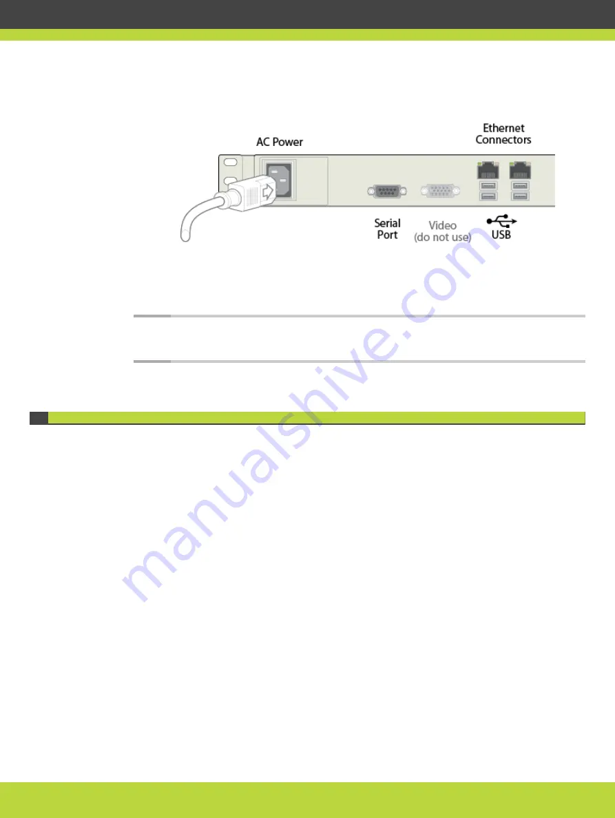
Figure 4-9
Rear panel of the device
Step 2
Connect the other end of the power cable to the mains.
Step 3
Use a serial cable to connect a PC to the device's serial port. This connection is required for
local configuration and maintenance.
Note
Do not connect a screen or a keyboard to the device directly. Define the device's
basic settings via the serial connection only.
Setting the IP Address of the Device
Use the serial port on the back panel of the device to connect it directly to a PC to assign an
IP address. You must assign the IP address before you connect the device to the network.
Before you begin
Make sure you have these items:
•
Dedicated IP address for the device
•
Dedicated subnet mask for the device
•
IP address of the default router which the device uses to communicate over the network
•
A PC with an available serial port. It should have terminal emulator software installed like
SecureCRT or PuTTY.
•
Serial cable provided with the device.
Procedure
Step 1
Connect the power cable but do not switch on the device.
Step 2
Connect the serial port to a PC with terminal emulator software.
Step 3
Start the terminal emulation application on the PC.
Step 4
Set the communication settings in the terminal emulation application on the PC as follows:
RADVISION | Deployment Guide for SCOPIA TIP Gateway Version 8.0
Setting up the SCOPIA TIP Gateway | 20


