Page 6 of 8
IN006 Rev G
2.2 OUTDOOR (BAND JOIST OR SIDEWALL)
1) Locate site for GP500 mounting. Use the
diagram in Figure 4 to assist in locating
the inlet hole for the unit.
2) Drill a 5.25" or 5.50" hole through the
band joist or sidewall.
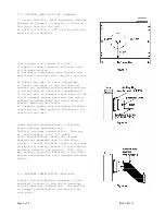
(Use Figure 5 as a Guide for 3-6):
3) Apply a liberal bead of silicone caulk
to the sealing ring.
4) Carefully feed power cord through hole
and install the unit into the hole drilled.
5) Insure the unit is level and plumb.
6) Insure the inlet of the fan does not
contact any building surface when mounting
to avoid noise or vibration transmission.
7) Secure unit to sidewall with four (4) #6
x 2.0" drywall screws provided. Use nylon
washers provided under the screw heads to
prevent marring the finish.
8) Complete piping run, providing flexible
couplings or other means of disconnect for
servicing the unit.
Under certain circumstances, a flexible
pipe coupling, RadonAway p/n
79019-1, may ease installation. This may
be particularly true of gable
side installations where the system
piping runs perpendicular to the floor
joists. Install the pipe coupling as shown
in Figure 6, making certain to avoid sharp
bends or kinks in the piping. (TIP: You
may connect the pipe coupling to the GP500
before installing the unit through the band
joist.)
2.3 MUFFLER INSTALLATION (Optional)
Install the vent muffler assembly in the
selected location in the outlet ducting.
Solvent weld all connections. The muffler
is normally installed at the end of the
vent pipe.
Summary of Contents for GP500
Page 1: ...Page 1 of 8 IN006 Rev G ...

