Page 2 of 22
IN052 Rev. K 0613
TABLE OF CONTENTS & FIGURES
1. PRE-INSTALLATION
.....................................................................................................................
1.1. Safety Matters
................................................................................................................................
1.2. Water Flow Requirements
................................................................................................................
1.3. Full Water Test
..............................................................................................................................
1.4. Unpacking and Locating System Components
.....................................................................................
1.4.1 Unpack All System Components
............................................................................................
1.4.2 Locate All Components
........................................................................................................
1.5 Use Qualified Technicians
................................................................................................................
2. INSTALLATION INSTRUCTIONS
................................................................................................
2.1. System Location
.............................................................................................................................
2.2. Preparing the System For Installation
...................................................................................................
2.3. Plumbing Hook-up
.........................................................................................................................
2.4. Electrical Hook-up
..........................................................................................................................
2.5. Vent Line Installation
......................................................................................................................
2.6. Remote Air Intake
..........................................................................................................................
2.7. System Start-up
.............................................................................................................................
2.8. System Check
................................................................................................................................
3. RETESTING
....................................................................................................................................
4. MAINTENANCE
.............................................................................................................................
4.1. Six Month Service (recommended)
.....................................................................................................
4.2. Annual Service (required)
................................................................................................................
5. TROUBLE SHOOTING
..................................................................................................................
6. ALARM SCHEMATIC
....................................................................................................................
7. BLOWER BRUSH REPLACEMENT
...........................................................................................
8. EQUIPMENT SPECIFICATION
...................................................................................................
LIMITED WARRANTY
.....................................................................................................................
3
3
4
5
5
5
5
6
7
8
8
10
12
13
14
14
15
16
16
16
17
18
19
20
21
22
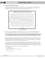
Figure 1 – Pump Curve
...............................................................................................................................
Figure 2 – Typical System
............................................................................................................................
Figure 3 – System Preparation
......................................................................................................................
Figure 4 – Pump Installation
........................................................................................................................
Figure 5 – Plumbing Arrangement
.................................................................................................................
Figure 6 – Rear View, Unit Only
...................................................................................................................
Figure 7 & 7a – Water Connections
................................................................................................................
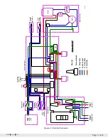
Figure 8 – Electrical Schematic
......................................................................................................................
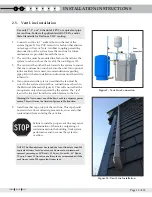
Figure 9 – Vent Line Connection
...................................................................................................................
Figure 10 – Vent Line Installation
..................................................................................................................
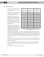
Table 1 – AIRaider™ Output vs. Well Pump Output
..........................................................................................
Figure 11 – Blower Enclosure, Front
..............................................................................................................
Figure 12 – Blower & Enclosure Cover
..........................................................................................................
4
7
8
9
9
10
10
11
13
13
15
20
20


