background image

  RadioLink Electronic Limited


www.radiolink.com


32 

Note: 

1.


You need to open the upgrade software and click Connect before you can press the power T8S button. If 

the T8S is turned on when or before you click “Connect”, it will cause connection failed.


2.


If you press T8S power button, but T8S cannot be turned on, this may be caused by firmware error. This 

problem can be solved by connecting the firmware upgrade software and upgrade the V835 or higher version 
firmware.   

If this still doesn’t work, please open the shell of T8S, disco

nnect the battery of the T8S, and then 

upgrade correct firmware. After the firmware is upgraded successfully, then connect the battery. 

Summary of Contents for T8S

Page 1: ...T8S BT FHSS User Manual 8 Channel Remote Controller APP Parameter Setting via Bluetooth Connection Compatible with Fixed wings Gliders Multirotors Cars Boats Robots CE FCC RoHS V2 0 ...

Page 2: ...Connection 7 2 1 3 Parameters Setup Menu 8 2 2 Software APP on Computer 9 2 2 1 Software APP Installation 9 2 2 2 Software APP Connection 9 Chapter 3 Function Setup Menu on APP 11 3 1 SERVO Menu 11 3 2 BASIC Menu 12 3 2 1 REVERSE 12 3 2 2 SBU TRIM 13 3 2 3 END POINT ADJUSTMENT EPA 14 3 2 4 FAIL SAFE F S 15 3 2 5 DELAY 16 3 2 6 AUX CH 16 3 3 ADVANCED Menu 17 3 3 1 D R Dual Rate 17 3 3 2 ATTITUDE 18...

Page 3: ...e corresponding joystick before operating the model If they are inconsistent please adjust before using 8 Please turn off the receiver and controlled equipment before stopping use and then turn off the power supply of the transmitter If the operation is reversed it may cause loss of control and cause an accident 9 T8S transmitter has a built in lithium battery with an operating voltage of 3 7V 4 2...

Page 4: ...ts and details R8SM Mini receiver 2 gram F121 Pro FPV Training Drone Wireless Trainer Cable Byme D Delta Wing Flight Controller 1 2 3 Transmitter Hardware Size 41 5 21 5 11 5mm 1 63 0 85 0 45 Weight 14g Channel Quantity 8 channels Control distance about 2000 meters in the air actual distance depends on the flight environment Operating Current 38 45mA 5V Operating Voltage 4 8V 10V DC Signals Output...

Page 5: ...n be set by parameter setting APP according to your needs and it is mostly used to control camera shutter 1 2 4 Transmitter Battery Charging The built in battery of T8S is 1S lithium When the voltage is low the green indicator will flash with a DD warning sound Make sure to charge the battery in time to avoid the possible damage by over discharge T8S charging is simple only need an android USB dat...

Page 6: ...M multi signal is blue light PWM mode All 8 channels of R8EF receiver output PWM signals SBUS PPM PWM mode The channel 1 of R8EF outputs the SBUS signal and channel 2 outputs the PPM signal Channel 3 8 output the corresponding PWM signal 1 3 2 Receiver Connection The connection wire for receiver is shown in the picture above The common ones are white red black wire or yellow red brown wire The two...

Page 7: ... of high precision Be careful to avoid strong vibration and high temperature Special vibration proof material for R C like foam or rubber cloth is used to pack to protect receiver Keeping the receiver in a well sealed plastic bag can avoid humidity and dust which would possibly make the receiver out of control Putting the receiver into a plastic bag can also prevent fuel and residue from entering ...

Page 8: ...ill pop out to ask for permission to turn on the Bluetooth function Click CONNECT on the top left of interface a list of devices will pop out for selection Select RadioLink device the two LED indicators at rightmost will flash with DD sounds Press any of the trimmer buttons to stop the DD sounds and the servo range will display on the APP meaning connection between the APP and T8S succeed Go to pa...

Page 9: ...starts reading the data in T8S Every time the APP is reopened the data displayed is the initial default value If the parameters are modified you need to click to READ again to display the modified data WRITE Click WRITE and three slow D sounds mean the modified data have been written successfully If no D sound means written failure please reconnect T8S to the APP and re write Click WRITE each time...

Page 10: ...d automatically when trying to create another new file sharing the same file name 2 2 Software APP on Computer 2 2 1 Software APP Installation Go to the official website https www radiolink com t8s_apps to download the computer software APP and run the program below If it s your first time to use computer parameter APP you need to install the driver before using it Please click the link below to d...

Page 11: ...P is reopened the data displayed is the initial default value If the parameters are modified you need to click to READ again to display the modified data WRITE Click WRITE and three slow D sounds mean the modified data have been written successfully If no D sound means update failure please reconnect T8S to the APP and re write Click WRITE each time parameter is modified to make sure it s well inp...

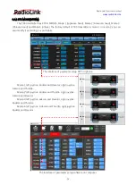
Page 12: ... basic channels and 4 auxiliary channels from left to right CH1 Aileron CH2 Elevator CH3 Throttle CH4 Rudder CH5 to CH8 Auxiliary channels There is a real time display when you are toggle any channel switch it is suitable for set up complex mix control functions The interface of parameter setup APP on phone The interface of parameter setup software on computer ...

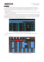
Page 13: ...ion is used to control several servos for fixed wing gliders e g V TAIL mix control make sure to set the phase in advance to avoid possible confusion The interface of parameter setup APP on phone The interface of parameter setup software on computer After changing the channel phase please check the control of the corresponding channel on the model to make sure the response direction of the channel...

Page 14: ...This function is used to set the neutral position of the servo not to set the servo surface to be horizontal This function is used to set the neutral position of the servo not to set the servo surface to be horizontal So the recommended steps are as follows Zero out the SUB TRIM when the servo is not connected to servo surface and adjust the neutral position of the servo through SUB TRIM Zero out ...

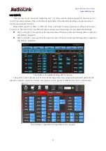
Page 15: ...ively small when you move the joystick to the maximum position You can increase the travel range percentage of the corresponding channel of the servo the maximum can be adjusted to 120 The default is 96 The interface of parameter setup APP on phone The interface of parameter setup software on computer EPA L and EPA R respectively represent the travel range on two sides of the neutral point You can...

Page 16: ...eeds set the servo travel range output by the channel After setting it the receiver will continue to output the servo travel range according to the value you set when the receiver loses the control of transmitter The interface of parameter setup APP on phone The interface of parameter setup software on computer Note 1 The setting of the throttle F S also applies to the low battery voltage F S valu...

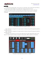
Page 17: ...per control whether the machine releases smoke or not etc Each auxiliary channel can be customized with one of three way switch toggle switch or push switch Any one of three way switch toggle switch or push switch can also be set to control different channels And the final effect can be seen on the SERVO MENU interface Note that If you flip any switch and two channels will change please check whet...

Page 18: ...ponding channel will be output in proportion to the move of the joystick The value can be set from 100 to 100 The change of the index will not change the maximum and minimum servo travel range When controlling the aircraft the index setting value is usually negative When the index is a negative value the greater the negative value the lower the sensitivity of the joystick in the neutral position a...

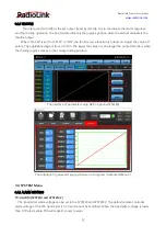
Page 19: ...7 will be used by default to control the output of the attitude channel The values behind each channel means different control percentage output different control signals The default values of T8S of each attitude is corresponding to the values of flight controller PIXHAWK MINI PIX APM TURBO PIX That is when the above flight controllers are used with T8S attitude can be selected on the Mission Pla...

Page 20: ...CH 1 and CH2 will respond and servo travel range can be adjusted individually AILE 1 and ELEV 2 correspond to the response rate of channel 1 when performing aileron operation and elevator operation AILE 2 and ELEV 1 correspond to the response rate of channel 2 when performing aileron operation and elevator operation The interface of parameter setup APP on phone The specific value is the amount of ...

Page 21: ...nd and servo travel range can be adjusted individually The interface of parameter setup APP on phone ELEV 1 and RUDD 2 correspond to the response rate of channel 2 when performing elevator operation and rudder operation ELEV 2 and RUDD 1 correspond to the response rate of channel 4 when performing elevator operation and rudder operation The specific value is the amount of servo travel range when t...

Page 22: ...rn off the main control under certain circumstances e g For dual engine aircraft turn off a motor or speed up down one motor to assist rudder to turn MAS Master channel Other channels need to cooperate with movements of the master channels SLA Slave channel Many mix controls are controlled by one master channel You can turn the MIX from INH to ON and set master channel slave channel Set UP and DOW...

Page 23: ...justable range is from 0 to 100 The larger the value it is the larger the output throttle is when the throttle joystick moves to the corresponding position The interface of parameter setup APP on phone SYSTEM The interface of parameter setup software on computer Advanced Menu 3 3 4 SYSTEM Menu 3 4 1 ALARM SETTINGS TX ALARM SYSTEM and SYSTEM 2 The transmitter alarm voltage can be set in the SYSTEM ...

Page 24: ...efault signal strength alarm value of the T8S is 100dBm You can set a reasonable value according to the actual situation to prevent the model from losing control due to weak signal When the RSSI goes lower than value you set T8S will make D sound to warn The best RSSI ALM is depends on the control range test at your flying area For example you have tested the control distance of your T8S is 2000 m...

Page 25: ...fy it according to your habits The interface of parameter setup APP on phone Mode 1 left joystick Rudder and Elevator right joystick Aileron and Throttle Mode 2 left joystick Rudder and Throttle right joystick Aileron and Elevator Mode 3 left joystick Aileron and Elevator right joystick Rudder and Throttle Mode 4 left joystick Aileron and Throttle right joystick Rudder and Elevator The interface o...

Page 26: ...SET This function is to restore the factory setting when necessary When press this RESET button T8S will make three slow D sounds meaning default setting is set The interface of parameter setup APP on phone The interface of parameter setup software on computer ...

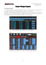
Page 27: ...the current T8S version number Since T8S was updated multiple versions before the new firmware is not fit for all versions of T8S Therefore please check your current firmware version before upgrading the firmware If the firmware is not necessary and the T8S transmitter can be used normally then there is no need to upgrade The interface of parameter setup APP on phone SYSTEM 1 The interface of para...

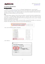
Page 28: ... software you can skip this step Note 1 When the firmware upgrade tool fails to detect the COM port it may be caused by not installing the driver or because you use USB charging cable wrongly instead of a USB data cable The T8S remote controller packing list is equipped with a USB data cable which can be charged and it can also use for computer parameter setting and firmware upgrade 2 Please note ...

Page 29: ...onic Limited www radiolink com 28 After the installation is complete The drive is successfully pre installed in advance will pop up If Driver install failure appears please uninstall the driver and reinstall the driver ...

Page 30: ...re Go to https radiolink com t8s_firmwares to download T8FB T8S_APPForFirmwareUpgrade ComputerOnly zip and unzip it connect T8S transmitter connect to the computer via a USB data cable then open the unzipped folder Click the T8FB T8S_APP for firmware upgrade exe program Choose correct COM port ...

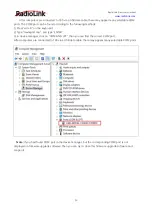
Page 31: ... the keyboard 2 Type devmgmt msc and type ENTER 3 In device manager click on COM AND LPT then you can find the correct COM port After computers are connected to T8S via a USB data cable there may appear many selectable COM ports Note If you had found COM port in the device manager but the corresponding COM port is not displayed on firmware upgrade software Then you can try to close this firmware u...

Page 32: ...en the Disconnected will change to Detecting This indicates that the firmware upgrade software has entered the detection state After entering the detection state short press the T8S power button then Detecting will turn to Connected which means that the firmware upgrade software is successfully connected to T8S ...

Page 33: ... connection failed 2 If you press T8S power button but T8S cannot be turned on this may be caused by firmware error This problem can be solved by connecting the firmware upgrade software and upgrade the V835 or higher version firmware If this still doesn t work please open the shell of T8S disconnect the battery of the T8S and then upgrade correct firmware After the firmware is upgraded successful...

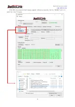
Page 34: ...RadioLink Electronic Limited www radiolink com 33 After T8S connected with the firmware upgrade software successfully click the APROM button to select the correct firmware ...

Page 35: ...t When the green PASS appears it means that the firmware flashing is successful Thanks Thank you for purchasing RadioLink 8 channels remote controller T8S Please read the manual carefully and set up the device as instructed steps If any problems found during the operation process contact your local dealer or contact us by e mail at after_service radiolink com cn Visit our website at www radiolink ...

Reviews: