RadioLink Mini Pix User Manual Download Page 25


25 


3.6 Flight Modes 

Mini Pix has 20 flight built-in flight modes, 10 of which are regularly used. There are modes to 
support different levels/types of flight stabilization, a sophisticated autopilot, a follow-me system etc.         
Flight modes are controlled through the radio (via a transmitter switch), via mission commands, or 
using commands from a ground station (GCS) or companion computer.                                                                      
You can setup six flight modes once and max setup eight modes combine with AUX-CH (CH7 and 
CH8).                                                                                                                                                                             

Flight modes setting steps:                                                                                                                        

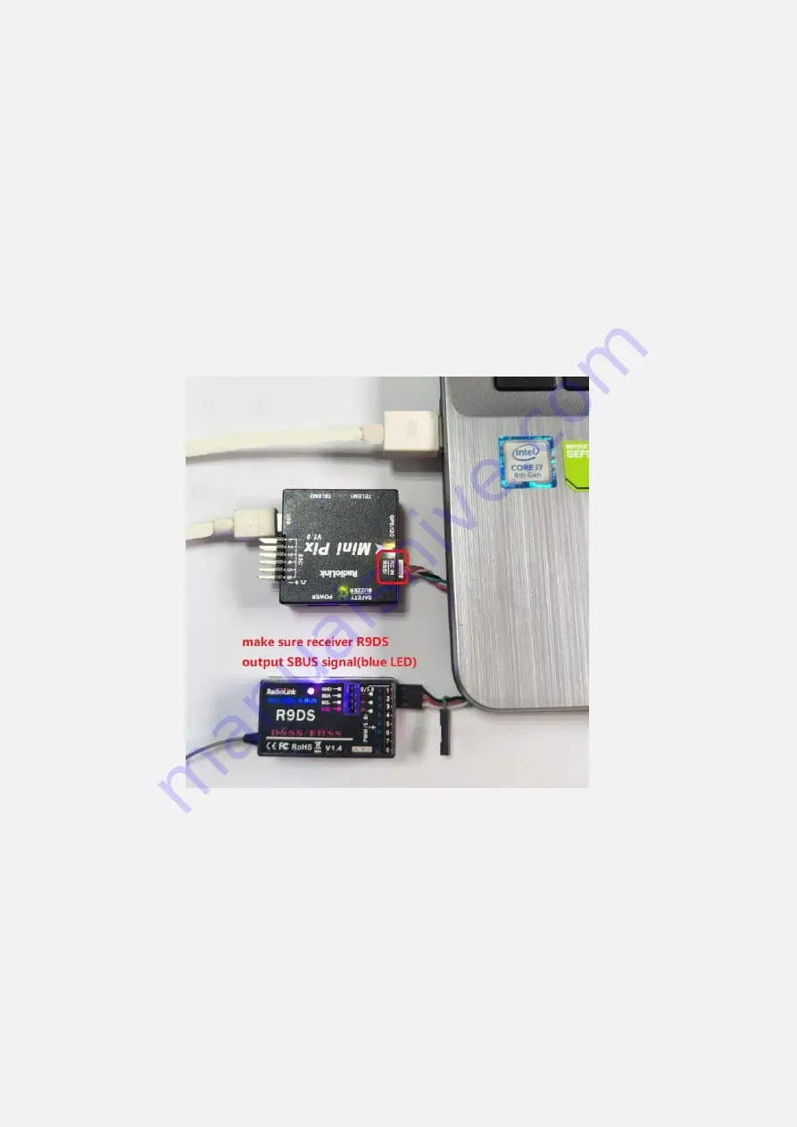
1. Connect MINI PIX and receiver (connect the RC port of MINI PIX, and make sure receiver work as 
SBUS signal).    

2. Make sure transmitter bind to receiver success.                                                                                                         
3. Make sure MINI PIX connect to Mission Planner success and click INITIAL SETUP

Mandatory 

Hardware

Flight modes, you can setup the flight modes you want in this menu.                                     


Summary of Contents for Mini Pix

Page 1: ... introductions about how to setup with transmitter AT9S more details about how to use flight controller PIXHAWK series can from this website http ardupilot org copter docs initial setup html Please start here for getting service if you have any questions during using the MINI PIX www radiolink com Phone 86 755 88361717 882 Email after_service radiolink com cn after_service1 radiolink com cn ...

Page 2: ...3 6 Flight Modes 25 3 6 1 Stabilize Mode 27 3 6 2 Acro Mode FPV 28 3 6 3 Altitude Hold Mode 29 3 6 4 Auto Mode 30 3 6 5 PosHold Mode 32 3 6 6 RTL Mode 33 3 6 7 Simple and Super Simple Modes 35 3 6 8 More Flight Mode 38 4 FailSafe Setting 39 4 1 Radio FailSafe setup 39 4 2 EKF FailSafe Firmware MPV3 2 1 44 5 Optional Hardware Setup 45 5 1 Install Mini Pix on Drone 45 5 2 Connect the Spare Parts 48 ...

Page 3: ...re when flight The main board has air pressure vent to ensure the accuracy of the barometer testing Shell design and vibration damping by software make Radiolink mini PIX achieved better Altitude Hold effect Based on the mature research and development of PIXHAWK we take about one year to reanalyze and retest all the functions of all the models including fixed wing multicopter and helicopter make ...

Page 4: ...4 1 2 Connectors ...

Page 5: ...5 Parameters ...

Page 6: ...nd then set up the physical hardware and Windows device drivers You can connect the PC and autopilot using USB cables Telemetry Radios Bluetooth IP connections etc 3 Download the update firmware by USB cable if you need 4 Connect Mission Planner to AutoPilot and then connect receiver to AutoPilot to finish the calibration of transmitter Accelerometer and compass 5 Setup RC transmitter flight mode ...

Page 7: ...t Framework 4 6 2 automatically when you click this website Then you need download Mission Planner you can download from our website www radiolink com Open the Microsoft installer file and select Run to run the installation utility ...

Page 8: ...setup CONFIG TUNING including detailed PID setup and parameters change SIMULATION make MINI PIX work as a simulator after upgrade a special simulation firmware HELP you can get help when you have questions about MP 3 Initial Setup First you have to upgrade the firmware you need when you the first time ready to use MINI PIX Radiolink Mini Pix is default with quadcopter firmware you have to install ...

Page 9: ...as missed the reset signal 3 If there s without firmware version number it means failed upload new firmware It may cause of network problem please re upgrade firmware until shows the version Click Yes to install the firmware Disconnect the USB cable click OK and then reconnect USB cable immediately Pay attention Mini Pix will have failed to connect if there are more than one COM please remove othe...

Page 10: ...ter disarmed Please click CONNECT to connect your Mini Pix and computer when firmware has installed successful Click CONNECT and it turns to green means connect successful Pay attention Please set Layout from Basic to Advanced in CONFIG TUNING menu if comes out three questions as below when you installing the Mission Planner ...

Page 11: ...11 1 It takes a long time to read the parameters 2 There are not have Load custom firmware and Pick previous firmware 3 INITIAL SETUP menu missed some parameters 3 2 Frame Type Please setup as below ...

Page 12: ...ardware Frame Type 3 Choose Quad or Hexa or other frame types as you need 3 3 Accelerometer Calibration Make sure the Mini Pix is keeping horizontal when do the accel calibration 1 Place vehicle level and press any key to save setting ...

Page 13: ...13 2 Place vehicle on its LEFT side and press any key to save setting 3 Place vehicle on its RIGHT side and press any key to save setting ...

Page 14: ...14 4 Place vehicle DOWN and press any key to save setting ...

Page 15: ...15 5 Place vehicle UP and press any key to save setting 6 Place vehicle on its BACK and press any key to save setting ...

Page 16: ...l the progress bar of Mag 1 to the end and comes out the MAG_CAL_SUCCESS marked words 2 with GPS use external and internal compass Calibrate interface will shows as picture below when use with GPS If the GPS mounted with the same direction with flight controller then it need not to setup the direction of GPS in MP but if you mounted the GPS with the different direction of MINI PIX you have to setu...

Page 17: ...een LED indicate same direction as the flight controller The green LED will flicker when TS100 have Keep the same direction with flight controller positioning Please fixed Mini Pix and TS100 then click Start and turn Mini Pix and TS100 till the progress bar of Mag 1 and 2 to the end and comes out the MAG_CAL_SUCCESS marked words ...

Page 18: ... Calibrate the compass as these steps below Hold the vehicle in the air and rotate it slowly so that each side front back left right top and bottom points down towards the earth for a few seconds in turn ...

Page 19: ... connect success The mission planner will remind you when the compass has calibrated success Click OK and then reconnect MINI PIX to computer compass calibrate success after restart the MINI PIX Attention 1 when the progress bar moves to 100 and then restart from 0 it may because of the wrong calibrate action or interference You can have a try to calibrate again till compass calibrate success or s...

Page 20: ...controls channels is a straightforward process simply move each of the enabled sticks switches through their full range and record the maximum and minimum positions There are two main transmitter configurations Mode 1 left stick controls pitch and yaw the right stick will control throttle and roll Mode 2 left stick controls throttle and yaw the right stick will control pitch and roll Copter defaul...

Page 21: ...21 For safety you should disconnect the battery and or remove propellers before preforming radio calibration ...

Page 22: ...R press Push button 1 second press Push button again when the display hints Are you sure you will find out DDD sounds come out with Please wait the mode type MULTIROTOR have setup success after the DDD sounds have finished 2 Setup CH3 THRO REV in REVERSE menu setting steps Press Mode button about one second to into BASIC MENU and then turn the dial to choose REVERSE press Push button to into the R...

Page 23: ...er are powered on and connected and the motor of your drone does not have power and without propellers And then click OK and move all RC sticks and switches to their extreme positions so the red bars hit the limits If the red bars have not any change when you move the sticks please check the receiver have connect success or not make sure the receiver maybe R9DS is output SBUS signal the blue LED o...

Page 24: ...s below CH1 low position roll towards the left up position roll towards the right CH2 low position pitch forward up position pitch backwards CH3 low position reduced speed up position speed up CH4 low position yaw towards the left up position yaw towards the right Click OK to save the radio calibration data ...

Page 25: ...ds or using commands from a ground station GCS or companion computer You can setup six flight modes once and max setup eight modes combine with AUX CH CH7 and CH8 Flight modes setting steps 1 Connect MINI PIX and receiver connect the RC port of MINI PIX and make sure receiver work as SBUS signal 2 Make sure transmitter bind to receiver success 3 Make sure MINI PIX connect to Mission Planner succes...

Page 26: ...1 is Stabilize the other five flight mode will be setup according to users flight habit First you have to setup flight mode in transmitter The setting steps as below 1 Power on and turn on your transmitter 2 Press Mode button twice to into ADVANCE MENU press Push button into ATTITUDE setting menu CH5 is default to the attitude control channel and please choose a 3 Posi SW and a 2 Posi SW to contro...

Page 27: ...oncentrate on too many controls at once 1 Pilot s roll and pitch input control the lean angle of the copter When the pilot releases the roll and pitch sticks the vehicle automatically levels itself 2 Pilot will need to regularly input roll and pitch commands to keep the vehicle in place as it is pushed around by the wind 3 Pilot s yaw input controls the rate of change of the heading When the pilot...

Page 28: ...atic leveling nor angle limiting performed by the autopilot 1 is automatic leveling The vehicle will automatically return to the level when the pilot releases the sticks The aggressiveness with which it returns to level can be controlled with the ACRO_BAL_ROLL and ACRO_BAL_PITCH parameters The default of 1 0 will cause it to return to level at up to 30deg sec Higher values will make it return more...

Page 29: ...ilots stick inputs that only applies to ACRO mode By default ACRO mode is much more responsive even in the center sticks positions than the other modes so this parameter allows the pilot to fine tune stick response in the control to match what they feel when they are in other modes such as Stabilize AltHold PosHold etc The default value of 0 applies 30 expo to Roll and Pitch demands from the pilot...

Page 30: ... or above 60 the vehicle will descend or climb depending upon the deflection of the stick When the stick is completely down the copter will descend at 2 5m s and if at the very top it will climb by 2 5m s These speeds can be adjusted with the PILOT_VELZ_MAX parameter The size of the deadband can be adjusted with the THR_DZ parameter AC3 2 and higher only This params value should be between 0 and 4...

Page 31: ...are acceptable and that the GPS is functioning well including returning an HDOP of under 2 0 AUTO should be set up as one of the Flight Modes on the flight mode switch Make sure that the GPS is positioning first The LED of Mini Pix is green The LED of GPS and compass module is blinking If starting the mission while the copter is on the ground the pilot should ensure the throttle is down then switc...

Page 32: ...r will return to the home position which is the location where the copter was armed As the copter touches down at the end of the mission the pilot should move the throttle to zero at which point the autopilot will disarm the motors if it also believes that it has landed 3 6 5 PosHold Mode The PosHold flight mode previously known as Hybrid is a new mode for AC3 2 It is similar to Loiter in that the...

Page 33: ...mply stops the vehicle as soon as possible using the Loiter controller Once invoked this mode does not accept any input from the pilot This mode requires GPS RTL mode Return to Launch mode navigates Copter from its current position to hover above the home position The behavior of RTL mode can be controlled by several adjustable parameters When RTL mode is selected the copter will return to the hom...

Page 34: ...lt return altitude Default is 15 meters 1500 2 RTL_ALT_FINAL The altitude the copter will move to at the final stage of Returning to Launch or after completing a Mission 1 Set to zero to automatically land the copter 2 The final return altitude may be adjusted from 0 to 1000 centimeters 3 RTL_LOIT_TIME Time in milliseconds to hover pause above the Home position before beginning final descent The L...

Page 35: ...imple and Super Simple Modes Simple and Super Simple modes allow the pilot to control the movement of the copter from the pilot s point of view regardless of which way the copter is facing This is useful for new pilots who have not mastered adjusting their roll and pitch inputs depending upon which way the vehicle is facing and for cases when the copter is far enough away that its heading is not a...

Page 36: ...l input right red the vehicle rolls to its right With the copter is facing in the same direction as the pilot it is relatively easy to control the vehicle but when the vehicle is facing towards the pilot an inexperienced pilot will feel that the controls are all reversed I e if the pilot inputs right roll the vehicle will move to the left from the pilot s point of view Simple Modes ...

Page 37: ... from you While flying you should try to keep the vehicle flying in front of its starting position because if it flies behind you all the controls will feel reversed As mentioned above simple mode is also very useful in emergency situations where the copter is far enough away that it is very difficult to determine its heading Super Simple Modes Super Simple mode is the same as simple mode except t...

Page 38: ...icle with the nose of the vehicle pointed at the center Drift Mode This page provides tips for flying in Drift Mode and methods for tuning your copter to fly optimally in Drift Mode Sport Mode Sport Mode is also known as rate controlled stabilize plus Altitude Hold Flip Mode Vehicle will flip on its roll or pitch axis depending upon the pilot s roll and pitch stick position Vehicle will rise for 1...

Page 39: ...ilot s RC transmitter and the flight controller s receiver is lost This page explains this failsafe s setup and testing Note the Radio failsafe was previously called Throttle failsafe because of the way in which some receivers use the throttle channel to signal the loss of contact Make sure transmitter and receiver connect success and work with SBUS signal F S setting steps Setup in transmitter se...

Page 40: ... and there are two ways that it can do this the method depends upon the receiver Low Throttle method the receiver pulls the throttle channel normally channel 3 to a value below the bottom of its normal range normally below 975 With the LiPo battery disconnected 1 Connect your flight controller to the mission planner and select Initial Setup Mandatory Hardware Failsafe 2 Set the Failsafe Options to...

Page 41: ...immediately if it loses RC contact Set the FS PWM value to be 1 at least 10 PWM higher than your Channel 3 s PWM value when the throttle stick is fully down and the transmitter is off 2 at least 10 lower than your channel 3 s PWM value when the throttle stick is fully down and the transmitter is on 3 above 910 Click OK to into the failsafe setting menu ...

Page 42: ...ailsafe function setup success the PWM of CH3 is smaller than 975 If enabled and set up correctly the radio Failsafe will trigger if 1 The pilot turns off the RC transmitter 2 The vehicle travels outside of RC range 3 The receiver loses power unlikely ...

Page 43: ... switch to another position and then back to Loiter Copter also supports Battery Ground Station and EKF DCM failsafes You can check your Failsafe by performing the following tests with the MINI PIX connected to the Mission Planner either via a USB cable or telemetry link You can complete these tests without plugging in your LiPo battery but if you do connect a battery you should first remove the p...

Page 44: ...ode displayed on the Failsafe page is updating appropriately Test 5 optional removing power from the receiver Switch to stabilize mode arm your motors and keep your throttle above zero Carefully disconnect the power wires connecting the receiver to the APM The Flight Mode should switch to RTL or LAND as described in Test 3 Warning unplug the APM so that it is powered down before reattaching the re...

Page 45: ...e and setup parameters as the steps above 3 press the safety switch and have a try to disarmed mount on the propellers if the drone can disarm success then you can go to flight 5 1 Install Mini Pix on Drone Mount the Mini Pix at the barycenter of the drone make sure the arrow of the MINI PIX is point to the front Keep the GPS with the same direction of MINI PIX if you need to use MINI PIX with GPS...

Page 46: ...46 Hexacopter Octocopter Y6 ...

Page 47: ...lers Pusher propellers are often marked with a P However not all propellers are marked and both types are often available in either rotational direction Therefore it is most reliable to recognize the correct propeller type by its shape as shown below Note that the propellers below have the edge with the shallow consistent curve at the leading edge in direction of rotation and the ...

Page 48: ... output port to the RC IN port of MINI PIX Buzzer and safety switch use a 5 pin GH connect wire to connect Safety Switch and Buzzer to the SAFETY BUZZER port to MINI PIX Power Module use a 6 pin GH wire to connect the power module to the POWER port of the MINI PIX GPS and compass use a 6 pin GH wire to connect the GPS TS100 for example to the GPS I2C port of the MINI PIX please make sure that GPS ...

Page 49: ...in the Mission Planner s INITIAL SETUP Optional Hardware Battery Monitor screen Enter the properties your module can measure the type of module the type of flight controller and the battery capacity Monitor Voltage and Current or Battery Volts Sensor Supported power module or Other APM ver Flight controller e g Pixhawk Battery Capacity Battery capacity in mAh The bottom section of the the Battery ...

Page 50: ...rom the hand held volt meter s reading by more than perhaps 0 2V you can correct the APM PX4 s reading by doing the following 1 On Mission Planner s INITIAL SETUP Optional Hardware Battery Monitor screen set the Sensor to Other 2 Enter the voltage according to the hand held volt meter in the Measured Battery Voltage field 3 Press tab or click out of the field and the Voltage Divider Calced value w...

Page 51: ...flash for a few seconds as the gyros are calibrated do not move the copter 3 The pre arm checks will run automatically and if any problems are found a MINI PIX will double blink the red arming light on a Pixhawk the RGB led will blink yellow 4 Check that your flight mode switch is set to Stabilize ACRO AltHold 5 Press the safety button until the light goes solid 6 If you are planning on using the ...

Page 52: ...ate by more than 2 meters This message is normally short lived and can occur when the flight controller is first plugged in or if it receives a hard jolt i e dropped suddenly If it does not clear the accelerometers may need to be calibrated or there may be a barometer hardware issue Compass failures Compass not healthy the compass sensor is reporting that it is unhealthy which is a sign of a hardw...

Page 53: ...sky or checking sources of GPS interference i e FPV equipment are moved further from the GPS Alternatively the check can be relaxed by increasing the GPS_HDOP_GOOD parameter to 2 2 or 2 5 Worst case the pilot may disable the fence and take off in a mode that does not require the GPS i e Stabilize AltHold and switch into Loiter after arming but this is not recommended Note the GPS HDOP can be readi...

Page 54: ...lead to confusion Check FS_THR_VALUE the radio failsafe pwm value has been set too close to the throttle channels i e ch3 minimum Check ANGLE_MAX the ANGLE_MAX parameter which controls the vehicle s maximum lean angle has been set below 10 degrees i e 1000 or above 80 degrees i e 8000 ACRO_BAL_ROLL PITCH the ACRO_BAL_ROLL parameter is higher than the Stabilize Roll P and or ACRO_BAL_PITCH paramete...

Page 55: ... or it will cause the drone roll over Turn of the function that spin when armed without speed when motors are armed and throttle is at zero If you connect the battery and armed the motors begin to have speed even though the throttle is at zero from the version 3 1 firmware It reminds you that MINI PIX is in service and please take care of the safety This function is very importance for the safety ...

Page 56: ... and the LiPo battery is disconnected ESC calibration steps 1 Turn on your transmitter and put the throttle stick at maximum 2 Connect the Lipo battery The autopilot s red blue and yellow LEDs will light up in a cyclical pattern This means the it s ready to go into ESC calibration mode the next time you plug it in 3 With the transmitter throttle stick still high disconnect and reconnect the batter...

Page 57: ...the drone not level when you put it horizontal as this picture You can setup as below to solve the problem Under Initial Setup Mandatory Hardware select Accel Calibration from the left side menu Click Calibrate Level to start the calibration 5 6 GeoFence ...

Page 58: ...r out or up If the copter breaches this backup fence for example if the vehicle is not set up correctly or the operator takes control but is unable to bring the copter back towards home the copter will be switched into RTL again and another backup fence an additional 20m further out will be created If the copter eventually flies 100m outside the configured fence distance the vehicle will switch in...

Page 59: ...the Action as RTL or Land 6 Set Max Alt to the altitude limit you want in meters 7 Set Max Radius to the maximum distance from home you want in meters This should normally be at least 50m Enabling the fence with channel 7 or 8 It is not necessary to set up a switch to enable or disable the fence but if you wish to control the fence with a switch please follow these steps 1 Go to the Mission Planne...

Page 60: ...t to ensure the copter never travels far outside the fence This behavior will occur regardless of the flight mode If a LAND sequence is not desired the pilot can retake control by moving the flight mode switch 7 The backup fences are created 20m out from the previous breached fence not 20m out from the vehicle s position This means if you choose to override the fence you may have less than 20m to ...

Page 61: ...unction Switch to Autotune to allow you to turn the auto tuning on off with the a switch 3 Remove the camera gimbal or any other parts of the frame that could wobble in flight 4 Select which combination of axis roll pitch yaw you wish to tune using the AUTOTUNE_AXES parameter 5 Set the autotune s aggressiveness using the AUTOTUNE_AGGR parameter 0 1 agressive 0 075 medium 0 050 weak normally start ...

Page 62: ... it will repeat forward and back 2 Use the roll and pitch stick at any time to reposition the copter if it drifts away it will use the original PID gains during repositioning and between tests When you release the sticks it will continue auto tuning where it left off 3 Move the ch7 ch8 switch into the LOW position at any time to abandon the autotuning and return to the origin PIDs 4 Make sure that...

Page 63: ...er RTL Auto try reducing the RC_FEEL parameter to 0 25 This smooths out the pilot s input Alternatively try reducing the AUTOTUNE_AGGR parameter it should always be in the range 0 05 to 0 10 and try again If the vehicle feels sloppy after the AutoTune try increasing the AUTOTUNE_AGGR parameter as high as 0 10 and attempt the autotune again All of the parameters of MINI PIX can setup in Mission Pla...

Page 64: ...h Log There are two ways to record your flight data With some exceptions the two methods record very similar data but in different ways Dataflash logs use the MINI PIX onboard dataflash memory which you can download after the flight On Plane and Rover dataflash logs are created soon after start up On Copter they are created after you first arm the copter Telemetry logs also known as tlogs are reco...

Page 65: ...65 More details about how to use PIXHAWK MINI PIX APM please check on this website http ardupilot org copter docs common mission planning html ...

Reviews: