background image


Digital BUS-WATCH

®

 SD40


Page 26 of 72 

Radio Engineering Industries, Inc. 

640434 -- Rev 0 -- 9/30/2011 

Physical Mounting Requirements 


L Bracket Mounting


Mount Locations,

Both sides typical


Figure 15: L Bracket Mounting 


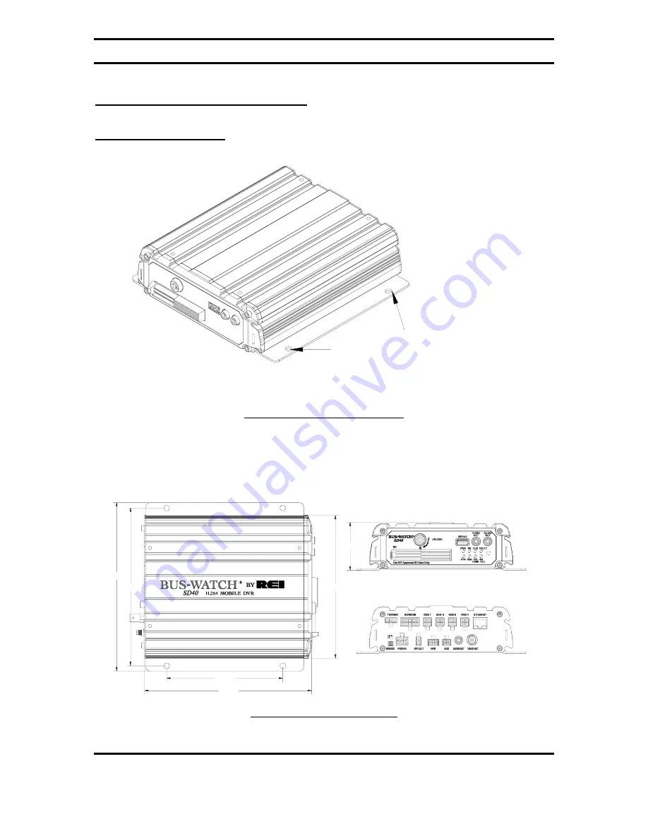
The DVR has two mounting brackets on the sides for easy mounting, as shown in 

Figure  15  above.  This  type  of  installation  is  recommended  for  vehicles  that  have  a 
secured compartment, such as a radio box, where the DVR cannot be tampered with. 
 

Rear View

Front View

7.93 in.

5.51 in.

8.00 in.

7.5 in.

6.77 in.

2.28 in.


Figure 16: DVR Dimensions 

Summary of Contents for Digital BUS-WATCH SD40

Page 1: ...Digital BUS WATCH Page 1 of 72 Radio Engineering Industries Inc 640434 Rev 0 9 30 2011 Digital BUS WATCH SD40 710292 Hardware User Manual Hardware Installation Manual...

Page 2: ...ading and Unloading 14 SD Card Record Times 16 Long Term Storage 17 Installation 18 System Wiring Power and Camera Cables 18 External Record Indicator Event Mark Button Harness 20 GPS Antenna Module H...

Page 3: ...s Viewing Angles 31 Recording Playback 33 System Start Up 33 System Shut Down 33 Playback Options 34 Menu Configuration 35 Installers Mode Page 35 Main Menu Page 36 Setup Menu 37 System Setup Menu 37...

Page 4: ...ket Mounting 26 Figure 16 DVR Dimensions 26 Figure 17 Security Cover Mounting 27 Figure 18 Camera Connection and Placement 28 Figure 19 Potential Single and Two Camera Placement Options 29 Figure 20 P...

Page 5: ...47 Alarm Settings 58 Figure 48 Audible Settings 59 Figure 49 Network 60 Figure 50 Ethernet Settings 61 Figure 51 Wi Fi Settings 62 Figure 52 3G Network Settings 64 Figure 53 Play Back Function 64 Fig...

Page 6: ...pact extruded aluminum housing low weight high temperature and vibration resistant Low voltage low current architecture designed for harsh mobile environments Removable SD Cards with tamper resistant...

Page 7: ...Video Retrieval and Archiving Ethernet port on the rear panel for easy video retrieval on the vehicle with a notebook computer Two sets of video and audio outputs for monitor viewing on the vehicle U...

Page 8: ...IDGE 710163 802 11G DVR 530073 ANTENNA CABLE ANTENNA 750243 FRONT CAP KIT OPT OPT REAR CAP KIT 750244 VIEW FRONT SD CARDS 16 GB 690632 32 GB 690633 530068 NETWORK CABLE AUDIO CABLE OPT ADAPTOR 110468...

Page 9: ...E I R SENSOR LED STATUS INDICATORS 8 INDICATORS USB 2 0 CABLE CONNECTION SD CARD SLOT DOOR CLOSED VIDEO OUTPUT CONNECTOR AUDIO OUTPUT CONNECTOR 3 5 6 4 1 2 FRONT PANEL LAYOUT 4 1 3 2 Use REI Approved...

Page 10: ...ETHERNET CABLE CONNECTION CAMERA INPUTS CAM 1 4 VIDEO OUTPUT CONNECTION GPS GPS RECEIVER CONNECTION ACC ACCELEROMETER MODULE CONNECTION ACCESSORY POWER POWER CABLE CONNECTION AUDIO OUTPUT CONNECTION 1...

Page 11: ...Digital BUS WATCH SD40 Page 11 of 72 Radio Engineering Industries Inc 640434 Rev 0 9 30 2011 Remote Control REMOTE 7 1 2 8 3 4 5 9 10 11 12 6 Figure 4 DVR Remote Control...

Page 12: ...OWN 6 LOGIN LOCK Access Menu 7 0 Quad Screen 8 ENTER Installers Mode 9 FWD Playback Function X2 X4 10 SETUP Menu 11 EXIT Exit Numeric 12 Playback Functions Figure 5 Remote Control Button Description U...

Page 13: ...Radio Engineering Industries Inc 640434 Rev 0 9 30 2011 NUMERIC INPUT KEYS Use the numbers to input values in the system setup screen or switch through the channels in live and playback modes Figure...

Page 14: ...g Inserting the SD Card Turn the SD card key to the unlocked and off position Slide the SD card door to expose SD card slot Insert the SD card into the slot all the way release and verify it is locked...

Page 15: ...e 15 of 72 Radio Engineering Industries Inc 640434 Rev 0 9 30 2011 Unlock door Use REI Approved SD Card Only BUS WATCH SD R UNLOCK Slide door open to access Card slot Figure 8 Removable Hard Drive Mod...

Page 16: ...60 721 1443 2886 HD1 FPS Quality 30 15 8 4 2 1 1 48 96 180 360 721 1443 2 64 128 240 481 962 1924 3 80 160 300 601 1202 2405 4 96 192 360 721 1443 2886 5 109 219 412 824 1649 3295 6 123 246 461 923 18...

Page 17: ...nd by mode if the systems are installed but not used for an extended period of time longer than 2 weeks it is recommended that the power be disconnected from the DVR to avoid draining the vehicle batt...

Page 18: ...harness P N 512008 is available Connect the camera s using cable P N 510781 or equivalent There is no specific orientation for camera cables to be installed If multiple types of cameras are installed...

Page 19: ...ection in case DVR configuration is changed in the future POWER TRIGGER VIEW REAR ETHERNET CAM 4 CAM 3 CAM 2 CAM 1 SENSORS ACC GPS 12V OUT POWER IGN VIA IGN SWITCH TO BATTERY TO BATTERY UNSWITCHED YEL...

Page 20: ...e 10 External Record Indicator Event Mark Button Harness Connection The optional Digital BUS WATCH external record indicator event mark button harnesses come in 2 different types of switches both in 2...

Page 21: ...he back of the DVR as shown in Figure 11 above This module will track up to twelve satellites at a time while providing one second navigation updates at low power consumption The GPS antenna module is...

Page 22: ...CONNECTION YELLOW RED WARNING VEHICLE SENSOR HARNESS OPT 512209 20 FT 512208 50 FT Vehicle Sensor Options Harness Figure 12 Vehicle Sensor Options Harness Connection The BUS WATCH Vehicle Sensor Optio...

Page 23: ...witch the polarity of these signals reference the Vehicle Sensor Levels Options menu page as shown in Figure 59 on Page 70 Speedometer Harness Wiring Instructions The BUS WATCH speedometer input wires...

Page 24: ...lamps Front and Back Doors Connect the BLUE and VIOLET wires to the switched side of the door switches On Screen Information with Vehicle Sensor Options Harness The Digital BUS WATCH Surveillance syst...

Page 25: ...the vehicle The reason for this is so that if external dampening is used for the DVR it will not throw off the Accelerometer readings To properly install the Accelerometer Module the user must align...

Page 26: ...s typical Figure 15 L Bracket Mounting The DVR has two mounting brackets on the sides for easy mounting as shown in Figure 15 above This type of installation is recommended for vehicles that have a se...

Page 27: ...ack of the DVR be enclosed in its own protective enclosure Security covers can be installed to protect the front and back of the DVR Slot Holes Front cover Holes Rear cover Tab Tab Front cover Rear co...

Page 28: ...this does not give a stable mount or it vibrates excessively Use outdoor cameras for exterior placement Figure 18 Camera Connection and Placement For a single camera installation it is common to plac...

Page 29: ...Digital BUS WATCH SD40 Page 29 of 72 Radio Engineering Industries Inc 640434 Rev 0 9 30 2011 Figure 19 Potential Single and Two Camera Placement Options...

Page 30: ...Digital BUS WATCH SD40 Page 30 of 72 Radio Engineering Industries Inc 640434 Rev 0 9 30 2011 INTERIOR 4 CAMERAS 4 CAMERAS EXTERIOR Figure 20 Potential Multiple Camera Placement Options...

Page 31: ...Digital BUS WATCH SD40 Page 31 of 72 Radio Engineering Industries Inc 640434 Rev 0 9 30 2011 Typical Camera Lens Viewing Angles Figure 21 4mm Lens Angles...

Page 32: ...Digital BUS WATCH SD40 Page 32 of 72 Radio Engineering Industries Inc 640434 Rev 0 9 30 2011 Figure 22 8mm Lens Angles...

Page 33: ...switch is connected to the ignition switch and the ignition switch is in the ON position Upon turning the system switch ON the Digital BUS WATCH will commence recording System Shut Down To stop the r...

Page 34: ...se The user can select individual video channels to be displayed full screen by pressing the numeric button on the remote corresponding to that channel or view all channels at the same time by pressin...

Page 35: ...creen text overlay mode is to give the installers an easy way to see some of the important information relating to the proper installation of the DVR Any of the vehicle sensor options that are being c...

Page 36: ...f the different options of the DVRs Video Search is where the user can play back video by choosing the specific Time and Date they would like to view Event Search allows the user to select video playb...

Page 37: ...n settings can be viewed or set using a video monitor and a remote control The Setup section of the Menu is subdivided into 4 main categories System Setup Video Setup Input Setup and Network System Se...

Page 38: ...VR model SERIAL shows the serial number and can be changed accordingly by using the remote control ORGANIZATION allows the user to enter custom information to identify the DVRs such as company name VE...

Page 39: ...has SD CAPACITY shows the total available space the SD card has DEVICE HISTORY shows the device status history including highest recorded speed miles logged hours logged maximum acceleration high low...

Page 40: ...rrow enter and numeric buttons on the remote control the user can change these settings DATE allows the user to manually enter the date and also to change the format of the date as it appears on the O...

Page 41: ...ct of 2005 changed the time change dates for Daylight Saving Time in the U S DST begins on the second Sunday of March and ends the first Sunday of November Because Congress retains the right to revert...

Page 42: ...n SD card is full and if the DVR is allowed to capture Meta Data Record Mode lets user to choose when DVR starts recording videos There are four settings for user to choose Ignition Schedule Both and...

Page 43: ...ill continue recording after the Record Mode expires DOWNLOAD DELAY The number of hours and minutes the DVR will stay on but not recording after Record Mode expires FILE LENGTH The length of videos ea...

Page 44: ...storage export import configuration export delete user log update main MCU firmware and set up password RESTORE SYSTEM DEFAULTS The user can restore DVR to factory default settings by using this func...

Page 45: ...start To update MCU firmware highlight MCU and press enter to start FW MCU VER Firmware version and MCU version PASSWORD PROTECTION Allows user to set a password on the DVR to prevent unauthorized en...

Page 46: ...Page 46 of 72 Radio Engineering Industries Inc 640434 Rev 0 9 30 2011 Video Setup Figure 35 Video Setup The Video Setup section of the menu is subdivided into 3 main categories Record Settings Live Se...

Page 47: ...lution frame rate etc GLOBAL VIDEO TYPE PAL or NTSC depending on which country the user is in VIDEO LOSS ALARM Allows the DVR to record as alarm video when there is a video loss CH ID Channel ID EN En...

Page 48: ...ts of the DVR RECORD PRIORITY Three preset record settings to allow user to choose between quality and space and one custom setting BALANCED Resolution CIF Frame rate 15 FPS Alarm frame rate 30 Qualit...

Page 49: ...VR processing power is used It shows ERROR when settings exceed processing power CURRENT SETTING The number of hours the current SD card can store under current record settings Live Settings Figure 38...

Page 50: ...to allow camera to be seen through network RES Resolution FPS Frame Per Second Figure 39 System Live Video Settings EN Allow cameras to be seen when set to ON RES Resolution CIF QCIF FR Frame Rate 30...

Page 51: ...ive OSD On it allows the item to show up on the live screen When Record OSD is set to on the item will be recorded into the video files MENU IDLE Time How long before the menu disappears automatically...

Page 52: ...network I D of the device WATERMARK When set to on date time and device ID will be hard coded to the video Input Setup Figure 41 Input Setup The Input Setup allows the user to customize the name that...

Page 53: ...e its own name and OSD abbreviation EN When set to ON sensor signal will be recorded to the video NAME The name of the signal Use remote to enter name OSD OSD abbreviation Use remote to enter abbrevia...

Page 54: ...y USB AUTO DOWNLOAD PRIORITY When set to on the highest priority video will be transferred to a USB storage first followed by the lower priority categories NETWORK AUTO DOWNLOAD PRIORITY 1 5 When set...

Page 55: ...eter Threshold The Accelerometer set up page allows user to set alarm threshold values and calibrate accelerometer ACCELEROMETER PORT FUNCTION When an accelerometer is connected to the DVR this settin...

Page 56: ...ter to calibrate accelerometer Figure 45 Temperature Threshold The Temperature setup page allows user to enable high low temperature alarm HIGH LOW TEMP ALARM When set to on the DVR will record an ala...

Page 57: ...set to GPS this setting will now show CALIBRATION To calibrate the vehicle speed sensor set the target speed and drive the vehicle at the same speed as the target speed press CALIBRATE to calibrate t...

Page 58: ...e alarm event before an alarm is triggered ALARM DURATION The length of triggered alarm before it times out During the duration if another same type of alarm is triggered the timer will be reset POST...

Page 59: ...r alarm is occurring AUDIBLE ALARM When set to ON the DVR will produce an audible beeping alert when an error or alarm is occurring SYSTEM ERROR When set to ON if there is a system error the DVR will...

Page 60: ...ull the DVR will produce an audible alert SD ERROR When set to ON if the SD card is not functioning the DVR will produce an audible alert Network Figure 49 Network The Network menu contains three cate...

Page 61: ...hree numbers needs to be the same as the local gateway IP address in order to have access to the DVR The last number must be set up independently on each DVR LOCAL SUBNET MASK A mask address is to use...

Page 62: ...1 Wi Fi Settings The Wi Fi network card settings allow the DVR to be connected wirelessly It also supports Auto IP detection for easy set up WIFI ENABLE Set to ON to enable Wi Fi WIFI IP ADDRESS The I...

Page 63: ...to find the wireless access point it needs to know the correct wireless network name for it to connect to Enter the wireless ESSID ADDRESS TYPE When set to Auto IP the DVR automatically finds an avai...

Page 64: ...s allow the DVR to connect to the network using 3G mobile network MOBILE NETWORK TYPE GPRS CDMA EVDO WCDMA EDGE TD SCDMA APN Please check this setting with network provider USERNAME Username for the n...

Page 65: ...user the ability to search videos by choosing the day and time The user also can filter out non event videos showing the ones that contains alarm events The upper half of the screen shows a calendar...

Page 66: ...ect Search the DVR will display a list of video files on the specific day during the specific time on the left part of the screen SEL Select videos by highlighting the box in the front and press enter...

Page 67: ...to the next page LAST Button Goes to the end of the video list To play a video simply highlight the video on the list and press enter on the remote During play back press enter on the remote to displa...

Page 68: ...select the videos that need to be exported then press EXPORT button external USB storage needs to be plugged in first EXIT button Exit file list page LOCK Lock selected videos so they will not be rem...

Page 69: ...o search on that day Once Event Type and Date are selected press Search to display the Event List Figure 58 Event List Page The Event List shows a list of videos that contains events on that day The l...

Page 70: ...remote During play back press enter on the remote to display OSD To go back to files list press exit on the remote Figure 59 Event List Page Extra The user also can export the event log and videos to...

Page 71: ...be easily upgraded in the field There are several ways this can be done through the Ethernet connection or through the front panel USB connection Front Panel USB Firmware Upgrade Create a directory n...

Page 72: ...ngs Frame Rate 1 to 30fps Selectable Audio Input 4 independent channel inputs Recording Modes Continuous Ignition Scheduled Event Triggered Playback Search by Alarm Date Time Camera Video Loss Detecti...

Reviews: