INSTALLATION INSTRUCTIONS
15
3.5 Water connections
In order to safeguard the heat exchanger and
circulation pump, especially in case of boiler
replacement, it is recommended that the
system is hot-flushed to remove any
impurities (especially oil and grease) from the
pipes and radiators.
Make sure that the domestic water and
central heating pipes are not used to earth the
electrical system. The pipes are totally
unsuitable for this purpose.
Isolation Valves must be installed on the
heating and D.H.W circuits. This will facilitate
all maintenance and service operations where
the boiler needs to be drained.
■ To prevent vibration and noise coming from
■ the system, do not use pipes of reduced diameter,
short radius elbows or severe reductions in the
cross sections of the water passages.
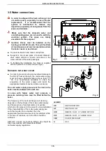
■ To facilitate the installation, the boiler is supplied
with an hydraulic connection kit (see fig.2).
Domestic hot water circuit
■ In order to prevent scaling and eventual damage to
the D.H.W heat exchanger, the mains water supply
must not have a hardness rating of more than 17.5
°Ck. It is nevertheless advisable to check the
properties of the water supply and install the
appropriate treatment devices where necessary
.
The cold water supply pressure at the inlet to the
boiler must be between 0.5 and 6 bar.
In areas with higher water inlet pressure a
pressure reducing valve must be fitted before the
boiler.
The frequency of the heat exchanger coil cleaning
depends on the hardness of the mains water supply
and the presence of residual solids or impurities,
which are often present in the case of a new installation.
If the characteristics of the mains water supply are
such that require it to be treated, then the
appropriate treatment devices must be installed, while
in the case of residues, an in-line filter should be
sufficient.
All D.H.W. circuits, connections, fittings, etc. should be
fully in accordance with relevant standards
and water supply regulations.
LEGEND
HR
HEATING RETURN
HF
HEATING FLOW
RCR
REMOTE D.H.W. CYLINDER RETURN
RCF
REMOTE D.H.W. CYLINDER FLOW
CWI
COLD WATER INLET
G
GAS
HF
G
HR
31
148
49
1
0
5
110
35
2
0
RCR
RCF
80
102
CWI
Fig. 2
Fig. 1
HR
G
CWI
HF
HWO


