


54
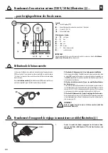
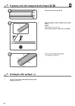
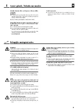
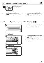
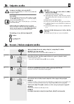
Connecting an external button (230 V/50 Hz) (Figure
m
) ...
... for the subsequent adjustment the limit stops
IMPORTANT
Disconnect the external button again once the limit stops have been adjusted and connect the
setting wire (
j
)
to the neutral conductor
(f)
, see figure
k
.
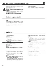
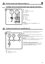
Using the setting wire
The setting wire
(
j
)
is used to transfer the motor set button
(11)
function to the
outside. If the setting wire
(
j
)
is connected to an external button (see above), this
external button can be used as a set button for adjusting the limit stops.
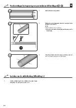
Guide the
setting wire (
j
)
of the motor cable
(15)
to the respective switch (e.g.
to the switch box).
(22)
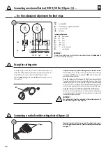
Using the setting wire (
j
) when installing the device for the first time
When installed for the very first time, the roller shutter fitter can connect the entire
motor supply cable
(15)
to a switch setting device
(22)
which can then be used to
adjust the tubular motor limit stops.
Using the setting wire (
j
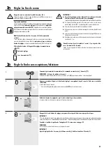
) to change the limit stops retrospectively:
If you want to change the limit stops of an existing roller shutter installation, all your
electrician needs to do is to connect the setting wire
(
j
)
to a conventional external
switch (230 V/50 Hz) in accordance with the connection diagram
m
. This switch
can then be used in conjunction with your shutter control device to change the limit stops.
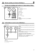
Using the setting wire (
j
) after having adjusted the limit stops:
Once the limit stops have been adjusted, the relevant external switching device
must be disconnected and the motor must be connected again in accordance with
the connection diagram, see figure
k
.
IMPORTANT
The setting wire (
j
) must be connected to the neutral conductor (f)
once the limit stops have been adjusted.
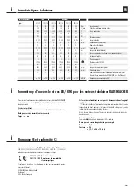
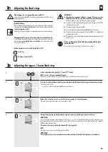
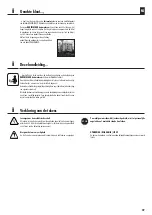
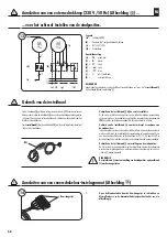
Connecting a corded switch-setting device (Figure
n
)
1.
Open the terminal contacts by pressing the plungers and connect
all of the tubular motor cable (15) cores according to their functions,
see figure
j
.
(a)
13
(d)
(e) (f)
(g)
(
j
)
(b)
(c)
(h)
(i)
(k)
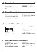
Key
(a)
= Set button
(11)
(b)
= Control device (e.g. single-pole switch/button)
(c)
= Main 230 V/50 Hz
(d)
= Switch box
Terminal configuration
(e)
=
PE
green/yellow
(f)
=
N
blue
(g)
=
L1
black
(h)
= (
▲
) black
(i)
= (
▼
) brown
(
j
)
=
white (Setting wire)
(k)
=
external button
EN
Plunger
14


