background image

11

EN

B

C

A

L

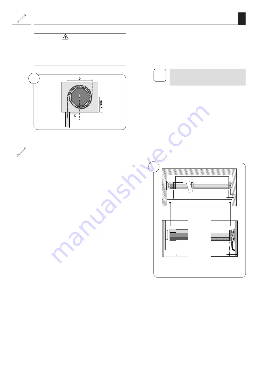
L = A - (B + C)

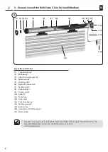
4

C

B

3

= (D/2)

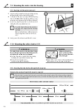
7.2  Mounting the bearings

  ATTENTION!

A roller shutter wound at an angle can block the 
drive and cause damage.


Always ensure that the bearings are mounted as 
horizontal as possible.

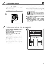
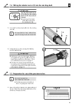
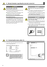
7.3  Determining the length of the winding shaft (5)

1. 

Measure the wall gap of the drive 

(13)

 and counter 

bearing 

(1)

 as shown.

2. 

Measure the roller shutter box and calculate the 
required shaft length 

[ L ]

.

3. 

Length of the winding shaft: 

L = A - (B + C).

Recommendation

Shorten 

L

 by approx. 

5 mm

 more than calculated 

by the equation to ensure a sufficiently large space 
of 2 to 3 mm in the overall length when the roller 
capsule 

(4)

 is inserted.

4. 

Shorten the winding shaft 

(5)

 to the required size.

Cut the shaft to size with a hacksaw at a right-angle. 
Remove the burrs from the shaft internally and ex-
ternally with a file.

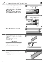
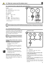
1. 

First determine the position of the drive 

(13)

 and 

counter bearing 

(1)

 in the roller shutter box.

2. 

Wind the roller shutter casing fully onto the winding 
shaft and measure the diameter 

[ D ]

. See figure 

[ 3 ]


for determining the position of the centre of the 
bearing to the guide rail.

i

  When installed, the wound roller shutter 

must run vertically in the guide rail on the 
window.

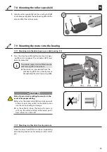
3. 

Fasten the bearing in accordance with the bearing 
type and on-site conditions.

4. 

Mount the drive bearing

 (13)

 so that the set button 

(11)

 on the drive head will be easily accessible at 

a later stage and the motor cable 

(15)

 can be laid 

without kinking.

B

 = Counter bearing / roller capsule

C

 = Drive bearing / motor

Summary of Contents for RolloTube CLIS

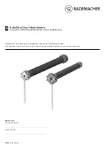
Page 1: ...be C line Small CLIS Medium CLIM Item numbers 2240 06 56 2240 10 56 2260 10 56 2260 20 56 2260 30 56 2260 40 56 2260 50 56 Please note Site of installation Serial number RolloTube C line Tubular Motors Translation of the Original Operating and Assembly Manual EN ...

Page 2: ...tor into the bearing 15 7 9 1 Mounting into the drive bearing as a click bearing 13 15 7 9 2 Mounting in other drive bearing versions 15 7 9 3 Mounting into the counter bearing 1 16 7 10 Mounting the roller shutter 17 16 7 10 1Mounting the roller shutter with rigid shaft connectors 16 8 Safety information regarding the electrical connection 18 8 1 Connecting the motor cable 15 18 8 2 Electrical co...

Page 3: ...on 1 List i Further useful information Please read the respective manual Unauthorised handling or configuration i 1 This manual serves to describe the installation electrical connection and operation of RADEMACHER tubular motors of the RolloTube C line Small and Medium series Before you begin please read this manual through completely and follow all the safety instructions and assembly instruction...

Page 4: ...emaximumpermissiblerunningtimeforacycle may not be exceeded when the equipment is in operation For this reason the tubular motor has a running time limit KB transient operation of four minutes If the running time limit is triggered then the tubular motor must be left for at least 20 minutes to cool down Incorrect use leads to an increased risk of injury Train all personnel to safely use the tubula...

Page 5: ...olating device fuse must be per manently available for the electrical connection at the installation location Therollershuttermustrunupanddownsmoothly It should not jam Operational conditions for the self learning mode and for the correct functioning of the blockage detection The roller shutter must be mounted to the wind ing shaft with rigid shaft connectors 6 see page 16 The roller shutter must ...

Page 6: ...nd set for each direction of travel of the roller shutter Once this point has been reached the tubular motor switches off and the roller shutter stops Transient operation KB Tubular motors are not designed for continuous operation Transient operation defines the maxi mum permissible running time Magnetic ring The magnetic ring 18 is located in the drive head area 12 It is driven by the winding sha...

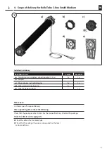
Page 7: ...etaining clip 1 x 1 x d Click universal drive bearing 1 x e Click ready box support 1 x Please note Customer specific scope of delivery After unpacking please check the following Check that the package contents matches the scope of delivery listed on the package Check the details on the type plate Check the details for the motor type Check that the voltage frequency corresponds to the local mains ...

Page 8: ...nding shaft 6 Rigid shaft connector 7 Retaining clip 8 Drive adapter 9 Tubular motor 10 Adapter 11 Set button 12 Drive head 13 Click drive bearing 14 Retaining spring 15 Motor cable 16 Controller z B Troll Comfort 17 Roller shutter The necessary accessories and all tubular motor controllers for this type of tubular motor incl the technical information and manuals can be found on our website www ra...

Page 9: ...s and stoppers in order to use the RolloTube C line in self learning mode see page 16 Overview of functions Self learning mode with a soft stop at both end positions see page 21 Torque monitoring Blockage detection in both directions of travel Quick and easy installation thanks to the short design Either one or both end points can be set manu ally as required Also in combination with the self lear...

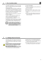
Page 10: ...ions depict the installation on the right hand side 7 1 Installation of the tubular motor Required minimum width for the roller shutter box Installingthetubularmotoratananglecancause thetubularmotororrollershuttertobedamaged For example a roller shutter wound at an angle can block the drive and cause damage Always ensure that the tubular motors and bear ings are mounted horizontally Please ensure ...

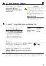
Page 11: ...rten the winding shaft 5 to the required size Cut the shaft to size with a hacksaw at a right angle Remove the burrs from the shaft internally and ex ternally with a file 1 First determine the position of the drive 13 and counter bearing 1 in the roller shutter box 2 Wind the roller shutter casing fully onto the winding shaft and measure the diameter D See figure 3 for determining the position of ...

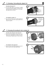
Page 12: ...he two retaining springs on the magnetic ring 18 downwards and pull the adapter 10 off the magnetic ring 18 Press the re taining springs downwards 7 5 Mounting dismantling the drive adapter 8 Dismantling the drive adapter 8 1 Releasetheretainingclip 7 fromthegeardriveshaft 19 and pull the drive adapter 8 off again Mounting dismantling the drive adapter 8 1 Slide the drive adapter 8 onto the gear d...

Page 13: ...shaft 5 will cause serious damage Never knock the tubular motor 9 with force into the winding shaft 5 1 First slide the drive adapter 8 into the winding shaft 5 i The motor 9 must have sufficient free space for winding shafts with internal felt 2 Subsequently press the winding shaft 5 fully onto the adapter 10 ATTENTION In doing so ensure that the adapter 10 does not slip off the magnetic ring 18 ...

Page 14: ...ons for the groove 1 are depend ent on the tubular motor type used see figures 3 Slide the tubular motor into the precision tube 4 Mark the four fastening holes and subsequently drill them through the precision tube into the drive adapter 8 Never drill deeper than 10 mm into drive adapter 8 ATTENTION Drilling in the area of the drive causes serious damage Never drill in the area of the drive 9 5 S...

Page 15: ...e drive bearing as a click bearing 13 1 Press the drive head 12 lightly into the click bear ing 13 until it engages The set button 11 must be easily accessible Hook the drive head 12 into the corresponding drive bearing and secure for example with a cotter pin 7 9 2 Mounting in other drive bearing versions WARNING WARNING Risk of short circuit resulting from water in the event of improper cabling ...

Page 16: ...ng 13 you may need to secure the drive with a secondary cotter pin 3 Correct any slight inaccuracies in size by means of sliding the roller capsule 4 in or out i The roller capsule 4 must be inserted at least 2 3 of its length into the winding shaft 5 Make sure that there is sufficient space in the axle length to ensure ease of move ment 4 Finally secure the roller capsule 4 with a screw 7 9 Mount...

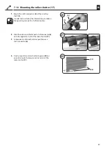
Page 17: ...nual for shaft connectors 4 Finally mount two roller shutter stoppers 20 or an end rail onto the lowermost slat or rail of the roller shutter 17 2 Slide the retainer profile for each shaft connector 6 onto the uppermost slat of the roller shutter 17 3 Subsequently slide each retainer profile over a shaft connector 6 7 10 Mounting the roller shutter 17 ...

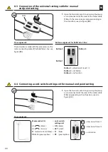
Page 18: ...les in the roller shutter box so that they cannot be damaged by moving machinery The mains connection for the drive may only be connected with the same conduction type Con sult customer services if necessary Fixed installation devices must be equipped on the installation side with a circuit breaker for each phase in accordance with DIN VDE 0700 Switches with a contact opening width of min 3 mm can...

Page 19: ...stment of the lower end point is required when using as an awning drive see page 21 RolloTube C line in parallel connection with other tubular motors The end points must be set for each other tubular motor in accordance with the respec tive operating manual Using rigid shaft connectors and stoppers RolloTube C line in self learning mode and tubular motors with automatic end point setting must be f...

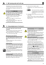
Page 20: ... PE green yellow direction of travel 1 direction of travel 2 no function ON 8 3 Connection of the universal setting cable for manual end point setting 1 Open the terminal contacts by pressing the plung ers and connect all of the wires of the motor cable 15 with the same colours and corresponding to their functions see also figure 23 Pin assignment Theconnectionismadewiththesamecoloursasthe motor c...

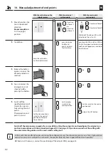
Page 21: ...ter the electrical connection 10 Manual adjustment of end points 1 Switch on the mains power supply The RolloTube C line is ready for operation imme diately 2 t Move the roller shutter up and down The end positions for the soft stop are automatically learned during the first drive cycles 3 Subsequently check the direction of travel of the roller shutter Switch the lines for the direction of rotati...

Page 22: ...oint is reached 4 You can correct the end point in small steps by briefly pressing the button 5 Switch off the specified direction of travel after success fully setting the end points The respective end point is stored 2 In addition With the cord switch setting unit With the set button on the tubular motor OR With the universal setting cable SET or ON SET or SET SET ON ON ON Direction of travel 1 ...

Page 23: ...ation it is neces sarytoconnectthetwocontrollinesforup s and down t separately to the phase L Verwenden Sie dazu entweder das im Fachhan del erhältliche neue Universal Einstellkabel 21 oder das ältere Schnurschaltersetzgerät oder einen externen Taster mit zwei Schaltkontakten The tubular motor may not be in operation Factory settings End points No end points stored Self learning mode with soft sto...

Page 24: ...tor has cooled down The tubular motor stops after a short period of time during the configuration and test proce dures Possible cause The adapter 10 may have slipped off the mag netic ring 18 on the drive head 12 Solution Checkthattheadapter 10 sitsflushwiththedrive head 12 and is fully inserted into the winding shaft 5 Slide the adapter 10 back so that it is flush with the drive head 12 and slide...

Page 25: ...atest after 180 seconds e g Basis for long term operation Basis 2 1 s Factor 86 2 1 s x 86 180 6 s Motor series CLIS xx xx PZ CLIM xx xx PZ Nominal torque Nm 6 10 10 20 30 40 50 No load speed rpm 28 16 16 16 16 16 12 Nominal voltage V 230 230 230 230 230 230 230 Frequency Hz 50 50 50 50 50 50 50 Nominal power W 121 121 112 145 191 198 205 Current consumption A 0 53 0 53 0 49 0 64 0 83 0 86 0 89 On...

Page 26: ...y with the Directives 2006 42 EC Machinery Directive and 2014 30 EU EMC Directive Warranty terms and conditions Information on our warranty conditions is enclosed separately with this product The full text of the EU declaration of conformity is included with the product and is kept on file by the manufacturer RADEMACHER Geräte Elektronik GmbH Buschkamp 7 46414 Rhede Germany i ...

Page 27: ...27 EN ...
Page 28: ...Subject to technical modifications misprints and errors Illustrations not binding RADEMACHER Geräte Elektronik GmbH Buschkamp 7 46414 Rhede Germany ...

Reviews: