background image

Dynalyzer – High Voltage Unit 

     OPERATION MANUAL 


13 

Summary of Contents for Dynalyzer IIIU

Page 1: ...RAPIDOSE Rapid Measurements with a super small footprint detector USER GUIDE DYNALYZER OPERATION MANUAL Dynalyzer IIIU High Voltage Unit ...

Page 2: ...e period of this warranty Radcal reserves the right to perform warranty services at its own factory Non Warranty Repairs The calibration of this instrument was correct within specified limits when the instrument left our factory Radcal cannot be responsible for injury or damage resulting from improper use or calibration errors which develop subsequent to our shipment of the instrument If Radcal de...

Page 3: ...Oscilloscope 16 Measurements with Digital Display 16 Current Measurements with Dynalyzer III Digital Display mA and mAs 16 Exposure Duration Time 17 Dynalyzer Digital Display of kVp Measurements 17 Filament Current Measurement with the Dynalyzer Digital Display 17 Measurements with Suitable RMS Voltmeter 17 Removing High Voltage Unit from X ray Installation 18 Interpreting Oscilloscope Measurement...

Page 4: ...oil or vaporizing compound on all high voltage connectors to prevent flashover 6 Keep away from x ray beam This system is designed for remote reading so the equipment should not be placed near the x ray beam path 7 Do not knowingly operate this unit in excess of 150 kVp or in equipment with unstable x ray tubes Severe damage to the equipment may result from an overvoltage condition 8 Be sure of yo...

Page 5: ...ects and provide frequency compensation In addition there is an oscillator which in conjunction with a high frequency isolation transformer located in the tank provides power to operate the anode current sensing system Anode Current Sensor The anode current sensor is an optically coupled device that is capable of providing an isolated signal that represents the anode current waveform The sensor is...

Page 6: ... Factory calibrated all output parameters traceable to National Bureau of Standards Electrical Rating maximum peak voltages Anode to cathode 150 kVp Anode to ground 85 kVp Cathode to ground 85 kVp Current from x ray to Generator max Anode peak 2 amps for 8 msec Anode continuous 100 mA Filament 10 amps ac rms D C Voltage Division Ration 10 000 1 1 10kV to 75 kV plus minus polarity Voltage Divider L...

Page 7: ...6 25 30 psig Gas Relief Valve 22 psig Gas Filling Valve Schrader type spring loaded Test Level Connectors Scope inputs 5 BNC type insulated Digital display 1 Bendix PT 02A 16 8P High Voltage Receptacles 3 conductor cables Receptacles conform to NEMA XR 7 1979 Coaxial Cable Two 12 foot long cables RG 58 U with BNC connectors Temperature Operating 15 to 30 C Storage 10 to 50 C Dimensions See Outline...

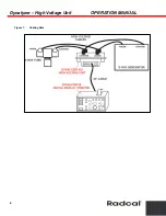
Page 8: ...Dynalyzer High Voltage Unit OPERATION MANUAL 6 Figure 1 Cabling Data ...

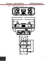
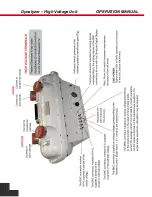
Page 9: ... Data dimensions in inches Calibration R Date Report Radcal Corporation By Due S N monrovia CA 91016 818 357 7921 FAX 818 357 8863 DYNALYZER U R DIVIDER VOLTAGE HIGH FIL Radcal Corporation R kV mA 9 00 13 26 12 97 0 37 8 13 3 21 1 26 0 63 24 75 22 88 5 19 5 19 3 21 ...

Page 10: ...roper techniques for the installation of the High Voltage Unit for calibrating or diagnostic investigation of an x ray installation The user is again cautioned about possible safety hazards due to the presence of high voltage x ray radiation and is requested to review the safety notice in the Preface Parts Necessary for Use Two 12 foot long RG 58U cables with BNC connectors at each end for oscillo...

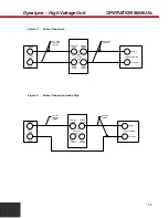
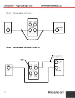
Page 11: ...ge Cable Connections The Dynalyzer III High Voltage Unit can be connected into the high voltage circuit in several ways Each configuration implements the best method of measurement for the particular selected application The following paragraphs outline these methods Series Connection Figure 3 This method is most often used since all x ray exposure parameters attainable with the High Voltage Unit ...

Page 12: ...ed cathode cable insertion The setup as shown in Figure 4 may also be employed in grid pulsed applications to accurately determine anode kVp and x ray tube current This technique does not measure cathode kVp or filament current because the cathode side of the Dynalyzer is not connected Series Parallel Connection This method can only be used with x ray generators having auxiliary high voltage recep...

Page 13: ... CATH TRANS ANODE ANODE TRANS TUBE VOLTAGE HIGH UNIT ANODE TRANSFORMER CATHODE CABLES VOLTAGE 5 FT HIGH EXISTING CABLES Figure 4 Series Connection Anode Only ANODE X RAY TUBE CATH TUBE CATH CATH TRANS ANODE ANODE TRANS TUBE VOLTAGE HIGH UNIT ANODE TRANSFORMER CATHODE 5 FT HIGH VOLTAGE CABLES CABLES EXISTING ...

Page 14: ...H TRANS ANODE ANODE TRANS TUBE VOLTAGE HIGH UNIT TRANSFORMER CATHODE CA 4 4 PIN HV CABLES Figure 6 Mammography Machine Connection GR DMR Only X RAY TUBE PLUG CATH TRANS DUMMY ANODE TUBE ANODE TRANSFORMER HIGH VOLTAGE UNIT TRANS CATH ANODE HV TEST POINT PMI H44 ADAPTER CABLE LORAD OR HOLOGIC OR PMI H0493 005 TUBE ANODE ...

Page 15: ...Dynalyzer High Voltage Unit OPERATION MANUAL 13 ...

Page 16: ...In order to guard against this possibility the user must be careful to angle the tube away from the HVU or close the collimator shutters Readout Oscilloscope a Measurement of kVp and exposure duration for both single phase and three phase machines may be read directly from the oscilloscope trace b Current measurements for radiographic exposures may be read from the oscilloscope trace Measurement p...

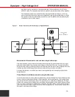
Page 17: ...urrent measurements can be easily obtained from the oscilloscope trace while single phase measurements will require some calculation A storage oscilloscope or oscilloscope camera will significantly aid in analyzing single phase measurements Three Phase Current Measurements using Oscilloscope Current measurements in three phase equipment may be read directly from the oscilloscope trace Figure 8 sho...

Page 18: ...the FLUORO position if there is significant low level noise filtering by the amplifier circuitry in the High Voltage Unit Measurements with Digital Display The Dynalyzer II or III Digital Display can be used in conjunction with the high voltage unit to provide the following five measurements simultaneously 1 mA and mAs 2 Exposure time triggered by kV mA external trigger or internal line trigger 3 ...

Page 19: ... phase and 75 for three phase operation A test exposure is made to set the gain factor of the display Each subsequent exposure will trigger both the peak detector circuit and the electronic time clock Both kVp and time in milliseconds will be displayed Current and filament will also be displayed A delay adjustable up to 20 milliseconds is provided to prevent measurement of the leading edge which m...

Page 20: ...connected to the High Voltage Unit readout terminal The waveform of the filament current will to some extent influence the accuracy of the reading of the peak reading as ac rectifier circuit used in most DVMs For low current level exposures the zeroing of the High Voltage Unit should be checked and adjusted if necessary through the access hole on the base Fluoro gain should be selected The limitin...

Page 21: ...20 second The kVp for this exposure would be the amplitude of area J The overshoot area E is not significant in this particular exposure because the dominant radiation is of the lower kVp value The peak value must not however exceed the rating of the tube of generator as it does contribute to the voltage stress on the system Although there is some deviation from this value the effective exposure t...

Page 22: ... causes These transient conditions may produce voltages which are considerably in excess of the kVp setting and may damage the x ray tube high voltage cables or high voltage transformer Transient voltages in the high voltage circuit may occur at a very high frequency so that the trace on the oscilloscope is very low in intensity or may not show at all with normal adjustments Whenever a pulse or po...

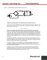
Page 23: ...identical to that of a single phase generator Evaluating Fluoroscopic Current Measurements The FLUORO mode should be selected for this test Circuit analysis would show that the system is an RC filter circuit Figure 11 If the High Voltage Unit is located near the transformer the current waveform will include the charging current of the cables With a capacitance of 30 pf ft a 50 foot cable will pres...

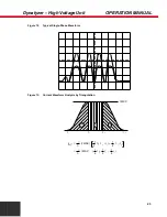
Page 24: ...iest approach would be to take 10 values of the current equally spaced in time in the period of one cycle and add them together and divide by ten The peak current is different in each pulse while the form factor or waveshape remains the same If graphical integrations are used at maximum accuracy the ratio of peak to average value of one pulse will be obtained and this ratio used to determine the a...

Page 25: ...Unit OPERATION MANUAL 23 Figure 12 Typical Single Phase Waveform Figure 13 Current Waveform Analysis by Triangulation I MAX 3 2 1 1 2 3 I 3 3 2 1 2 3 I I MAX 1 2 2 1 1 AV I I MAX 3 2 1 1 2 1 1 2 2 t t t t t t t t t t t t t t ...

Page 26: ... ray generators use saturable reactors or other non linear control means to control the current in the x ray tube filament This results in distortion of the input sine wave into a waveform approximating a square wave If this occurs the rms current would be equal to the peak current assuming a 100 conduction angle If the wave form is sinusoidal the rms current is 0 353 x the peak to peak current vi...

Page 27: ...f a rectified sine wave The use of these meters with phase controlled waveforms often found in SCR circuitry will be totally misleading as no change in voltage will be measured until the SCR is phased back to 90 or less If desired a graphical integration technique similar to that described for mA measurement may be used In the case of rms measurement divide one complete cycle 1 60 sec into 20 part...

Page 28: ...Dynalyzer High Voltage Unit OPERATION MANUAL 26 Figure 16 Calculation of RMS Current from Square Root of Sum of Square of N Intervals I RMS n n 1 N 2 N I In n I ...

Page 29: ...o position desired voltage on top left side Push board firmly into module slot 3 Rotate fuse pull back into normal position and re insert fuse into holders using caution to select correct fuse value CAUTION Before operating check that the operating voltage protection circuit is set for 240 volt operation Only the selections marked 120 and 240 are applicable Figure 17 Voltage Selection ...

Page 30: ...k due to other causes should be identified Recharging may be accomplished with the contents of a lecture bottle of Sulfur Hexafluoride C P gas available from Matheson Gas Products Company The contents of one lecture bottle of SF6 1 2 pound is adequate to completely fill the system As long as there is positive pressure in the High Voltage Unit purging of the unit will not be necessary Failure Modes...

Reviews: