background image

RACAL RA-237B 


Gerry O’Hara 


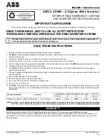
under this secondary cover (photo, below). 
 

Operation


With the RA-237B installed, I found its operation was very straightforward, and the switching 
between the normal RA-117 operation above 980kHz and with the RA-237B from 10kHz 
through 980kHz worked well (just remember to connect antennas to both the RA-117 and RA-
237B antenna sockets and to use the red scale on the RA-117).  The noise level was found to be 
good, however, sensitivity is a little lacking compared with the RA-117 in the segment of the 
spectrum covered by both (750khz to 1MHz), though seems to be to specification.  Unfortunately 
I do not have a real LF antenna set-up here, so no real-world on-air LF checking below around 
500kHz was possible (though it picks up my signal generator ok right down to 10kHz). 
 

Conclusion 

 
So, was it worth spending $110 on the RA-237B plus $20 on replacement parts? – I think it 
certainly was, if only for the entertainment value of getting it working, however, being able to 
cover the entire Broadcast band is useful and one day I may even string-up a real LF antenna… 
 

Summary of Contents for RA-237B

Page 1: ...ntial sources for one of these fairly scarce units over the past couple of years and finally found one for sale on Ebay locally here in British Columbia actually in the Okanagan which meant I would st...

Page 2: ...attenuator is provided together with a six band pre selector tuned circuit arrangement plus a wideband aperiodic input setting The latter can have a 500kHz low pass filter inserted if desired to bloc...

Page 3: ...file unit also mounted at the rear of the chassis photo below Passive components are mounted on posts inserted through Paxolin phenolic boards allowing easy replacement of components The pre selector...

Page 4: ...c and some silver mica capacitors in my RA 117 I decided to do the same for the RA 237B to promote long term reliability photos left and at top of following page All tubular ceramic caps tested ok and...

Page 5: ...perly and to allow set up and test however my RA 117 is located at one end of the basement and I don t have enough room in my miniscule workshop at the other end of the basement for it in its rather b...

Page 6: ...y originally written for the UK tube complement which uses 6F33 tubes in the balanced mixer Grid 3 is pin 6 and they forgot to change the text to suit the 6AS6 s fitted in the US version Grid 3 is pin...

Page 7: ...table I then re connected the RA 237B to the RA 117 and it was soon pulling in stations and lots of QRM from DC to 980kHz phew I had aligned the harmonic generator and balanced mixer in the workshop b...

Page 8: ...however sensitivity is a little lacking compared with the RA 117 in the segment of the spectrum covered by both 750khz to 1MHz though seems to be to specification Unfortunately I do not have a real L...

Page 9: ...cosmetic condition some with missing and or broken tag strips capacitors removed broken knob skirts missing decals etc The two best shape receivers were to be retained for the Museum s collection N8 w...

Page 10: ...he LF converter by the RA 117 this being switched in when operation below 980kHz is selected and simultaneously removed from the front end of the RA 117 Thus when the receiver LF converter is receivin...

Page 11: ...checked and found to be 500mA Tube screens were cleaned inside with acetone to remove brown residues scratches touched up with black permanent marker The knobs were cleaned with soapy water cut with...

Page 12: ...n the schematic between the two sections of the 2MHz bandpass filter after the harmonic generator absent in Serial No 179 This change is interpreted as improving the characteristics of the bandpass fi...

Reviews: