background image

1/16

Tel: (888) 552-6467                             Fax: (800) 316-4515

07/21 750.2158 Rev. B

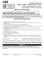
EMIU 400W - 4 Option Mini Inverter

i

IMPORTANT SAFEGUARDS

When using electrical equipment, basic safety precautions should always be followed, including the following:

READ THIS MANUAL AND FOLLOW  ALL SAFETY INSTRUCTIONS 
THOROUGHLY BEFORE OPERATING THE EMIU INVERTER SYSTEM

SAVE THESE INSTRUCTIONS

1. Install in accordance with the National Electrical Code and local regulations.
2. The 

EMIU

 contains potentially hazardous  voltages. Installation, maintenance  and service work should be performed by qualified 

and trained personnel.

3. Units to be installed only as per configuration described in this instruction manual.
4.

Electricians and end-users need to ensure product system compatibility before final installation.

5. The AC voltage rating of this equipment is specified on the product label. Do not connect the 

EMIU

 equipment to any other voltage.

6. All unused wires must be capped to prevent shorting. 
7. The 

EMIU

 should be mounted securely and in locations and at heights where it will not be readily subjected to tampering by 

unauthorized personnel.

8. The use of accessory equipment and replacement parts not recommended by manufacturer may cause an unsafe condition and will 

void the warranty.

9. Do not mount near gas or electric heaters.
10. Do not let power supply cords touch hot surfaces.
11.

D

o not use this equipment for other than its intended use.

12. DO NOT USE OUTDOORS. 

13.  The 

EMIU

 uses sealed valve regulated lead acid batteries. Batteries can be punctured if not handled properly, therefore use caution 

when servicing batteries.  In the event battery acid comes in contact with eyes or skin, flush with fresh water and consult a physician 
immediately.


NOTE: At 120Vac, unit is rated at power factor 0.8. For loads having a power factor below 0.8, unit capacity needs to be derated.

      At 277Vac, unit is rated at 0.9 power factor. For loads having a power factor below 0.9, unit capacity needs to be derated.

All ABB inverter products receive 100% quality inspection before shipment to ensure proper and satisfactory operation.

When operated under normal conditions, ABB inverter products will provide years of dependable service. This unit is backed by a 3-7 
year warranty. The unit is covered by a complete 3-year warranty against defects in material or workmanship, and a 7-year pro-rata 
battery warranty.

BEFORE CONTACTING TECHNICAL SUPPORT MAKE SURE TO FOLLOW ALL STEPS IN SEQUENCE AND REFER TO 
THE TROUBLESHOOTING GUIDE INCLUDED IN THIS MANUAL.

MODEL NUMBER

AC SPECS

EMERGENCY POWER AVAILABLE FOR LOAD

APPROX. 

WEIGHT

90 MIN

2H

3H

4H

EMIU 400 - 4 option

120/277 VAC, 60Hz

4.6 / 2.0 Amps

400W

300W

200W

150W

150lbs.

WARRANTY

EMIU 400W - 4 Option Mini Inverter

INTERRUPTIBLE EMERGENCY LIGHTING

UNIT INVERTER INSTRUCTION MANUAL

THIS UNIT CONTAINS A 

RECHARGEABLE VALVE-REGULATED  

LEAD ACID BATTERY. PLEASE 

RECYCLE OR DISPOSE OF 

PROPERLY.

Summary of Contents for EMIU 400W

Page 1: ...ot surfaces 11 Do not use this equipment for other than its intended use 12 DO NOT USE OUTDOORS 13 The EMIU uses sealed valve regulated lead acid batteries Batteries can be punctured if not handled properly therefore use caution when servicing batteries In the event battery acid comes in contact with eyes or skin flush with fresh water and consult a physician immediately NOTE At 120Vac unit is rat...

Page 2: ... BOTH NORMAL AND EMERGENCY SOURCES BY TURNING OFF THE A C BRANCH CIRCUIT AND BY DISCONNECTING THE BATTERY CAUTION ONLY ONE VOLTAGE IS ALLOWED 120V OR 277V CONNECTION TO MORE THAN ONE VOLTAGE MAY RESULT IN EQUIPMENT FAILURE AND VOID THE WARRANTY CAUTION THE MINI INVERTER HAS A SELF TEST FEATURE AND CAN ENTER IN SELF TEST MODE MONTHLY BIANNUAL OR ANNUAL AT ANY TIME WHEN THIS OCCURS POWER WILL BE AVA...

Page 3: ... Mini Inverter securely to the wall e Connect the conduit containing the AC supply and remote fixture leads to the Mini Inverter Use the provided knock outs on the side of the Mini Inverter for connecting the incoming wires f Install the batteries at this time but do not connect the battery leads until other wiring is completed STEP 1 MOUNTING THE MINI INVERTER TO WALL SEE FIGURE 1 WARNING THE MIN...

Page 4: ...all the loads to be powered by the Mini Inverter g If the voltage rating of the loads is 120VAC connect the red wire to the left terminal of TB1 h If the voltage rating of the loads is 277VAC connect the red wire to the right terminal of TB1 a Connect the Ground wire to the Ground Bus Bar b Identify the terminal block for UNSWITCHED INPUT figures 6 7 8 or 9 c Connect the NEUTRAL wire to the NEUTRA...

Page 5: ...ere applicable Perform all wiring procedures in accordance with applicable codes The unit is shipped configured to operate in Normally On mode by using an assembled jumper This jumper can be removed to configure the SWITCHED INPUTS as desired Do not connect the load to the Mini Inverter at this point of time a Position the batteries in the unit b Refer to figure 4 Connect the RED wire to the posit...

Page 6: ... wiring or call Technical Support a Turn off switch located on right hand side of inverter module b Turn off AC mains circuit breaker in the service panel feeding the Mini Inverter a Before proceeding confirm all circuits are de energized b Upon confirmation that measured output voltage of Mini Inverter matches voltage rating of loads wire load c Identify output terminal block refer to figures 6 7...

Page 7: ... unswitched will turn ON All normally off lamps shall also be ON After 1 minute test lamps will revert to their normal operating mode and unit will revert to recharge mode Status indicator will be steady ON green if no fault has been detected If a fault is detected refer to the FEATURES AND OPTIONS instructions on pages 12 to 14 for diagnostics and auto test features Allow the batteries to charge ...

Page 8: ...L 120Vac 277Vac UNSWITCHED INPUT OUTPUT LOAD SELECT THE CORRECT VOLTAGE AT TB1 CIRCUIT 3 HOT SWITCHED CONTROLLED NOT LINE CIRCUIT 4 CIRCUIT 2 CIRCUIT 1 HOT HOT HOT NOT LINE NOT LINE NOT LINE Neutral Hot CIRCUIT 4 3 2 1 USED USED USED USED CIRCUIT CIRCUIT CIRCUIT Neutral Hot Neutral Hot Neutral Hot CIRCUIT 4 CIRCUIT 3 CIRCUIT 2 CIRCUIT 1 Neutral Hot 120V TB1 LOCATION input FIGURE 6 NOTE WIRING DIAG...

Page 9: ...eutral Ground NEUTRAL 120Vac 277Vac UNSWITCHED INPUT OUTPUT LOAD SELECT THE CORRECT VOLTAGE AT TB1 CIRCUIT 3 HOT SWITCHED CONTROLLED NOT LINE CIRCUIT 4 CIRCUIT 2 CIRCUIT 1 HOT HOT HOT NOT LINE NOT LINE NOT LINE Neutral Hot CIRCUIT 4 3 2 1 USED USED USED USED CIRCUIT CIRCUIT CIRCUIT Neutral Hot Neutral Hot Neutral Hot CIRCUIT 4 CIRCUIT 3 CIRCUIT 2 CIRCUIT 1 Neutral Hot 120V TB1 LOCATION input UNSWI...

Page 10: ... UNSWITCHED INPUT OUTPUT LOAD SELECT THE CORRECT VOLTAGE AT TB1 CIRCUIT 3 HOT SWITCHED CONTROLLED NOT LINE CIRCUIT 4 CIRCUIT 2 CIRCUIT 1 HOT HOT HOT NOT LINE NOT LINE NOT LINE Neutral Hot CIRCUIT 4 3 2 1 USED USED USED USED CIRCUIT CIRCUIT CIRCUIT Neutral Hot Neutral Hot Neutral Hot CIRCUIT 4 CIRCUIT 3 CIRCUIT 2 CIRCUIT 1 Neutral Hot 120V TB1 LOCATION input UNSWITCHED SWITCHED INPUT OUTPUT INPUT F...

Page 11: ...UT OUTPUT LOAD SELECT THE CORRECT VOLTAGE AT TB1 CIRCUIT 3 HOT SWITCHED CONTROLLED NOT LINE CIRCUIT 4 CIRCUIT 2 CIRCUIT 1 HOT HOT HOT NOT LINE NOT LINE NOT LINE Neutral Hot CIRCUIT 4 3 2 1 USED USED USED USED CIRCUIT CIRCUIT CIRCUIT Neutral Hot Neutral Hot Neutral Hot CIRCUIT 4 CIRCUIT 3 CIRCUIT 2 CIRCUIT 1 Neutral Hot 120V UNSWITCHED SWITCHED INPUT OUTPUT INPUT FIGURE 9 NOTE WIRING DIAGRAMS HAVE ...

Page 12: ...ons when the unit ages Re initialization is not allowed if there is a lighting load failure alarm This is not applicable for units with No Auto Test plus No Load Detect option e SERVER FAILURE The Nexus server controller or PC is no longer communicating with the RF unit s modem Confirm Nexus server is operating and check whether other surrounding emergency lighting units are not powered If surroun...

Page 13: ... provide a 100 light level The Mini Inverter comes with four Lighting Control Override circuits In standby mode the Lighting Control Signal cables from the lighting fixtures are connected through relay contacts to the Lighting Control Signal cables from the external Lighting Dimming Control panel In emergency mode power failure the contacts of each relay open and the dimming signal from the lighti...

Page 14: ...f the cables refer to figure 12 Purple is positive and grey is negative Note Only one Lighting Control Override circuit has been shown for clarity The same principle applies to all four Lighting Control Override circuits 8 INVERTER ON DRY CONTACT The Mini Inverter also comes with one set of INVERTER ON Dry Form C contact The INVERTER ON Dry Contact is identified as INVON1 and its position is illus...

Page 15: ...d to the Nexus system Lamp load is OFF None if unit is in normally off mode Nexus option Unit is operating correctly Unit is not commissioned to the Nexus system LED flashing GREEN OFF Lamp load is ON None the unit is in test mode or is sampling load Unit is operating correctly Lamp load is OFF Inverter switched OFF Check the inverter ON OFF switch Turn it on Switch is located on the right side of...

Page 16: ...to complete annual test Replace batteries Battery fail in charge Replace batteries LED Flashing RED 2 times every 6 seconds Charger Failure Charger not working Reset unit see page 7 If same error is displayed replace charger board LED Flashing RED 3 times every 6 seconds Lamp Failure Loss of 10 or more of initial lamp load Replace the bad lamp and reset the unit Lamp Failure No output voltage Fuse...

Reviews: